How to Install Underfloor Heating for a Warm, Even‑Heat Home Upgrade
You’ll start your project to install underfloor heating by choosing electric mats/cable or hydronic tubing based on your heat load, floor covering limits, and required permits. For electric, you’ll provide a dedicated GFCI‑protected circuit, confirm breaker sizing, and meter‑check resistance, insulation, and floor sensor values before, during, and after embedding. For hydronic, you’ll plan loop spacing, install an accessible manifold, add mixing/limit and backflow protection, and pressure‑test for leaks. Next you’ll level, insulate, waterproof, embed, and finish. Keep going to see layout and commissioning steps.
Key Takeaways
- Choose electric or hydronic underfloor heating based on room heat load, floor type, and available electrical or boiler capacity.
- Verify permits, dedicated GFCI protection, correct breaker sizing, and manufacturer temperature limits before purchasing components.
- Prep a flat, dry, rigid subfloor; add approved insulation and moisture barriers to reduce heat loss and prevent failures.
- Lay mats/cables or tubing with proper spacing and clearances, protect sensors/leads, and pressure-test hydronic loops before covering.
- Test resistance/insulation and GFCI before, during, and after embedding; don’t energize until cured, then commission controls and document readings.
Electric vs Hydronic Underfloor Heating: Pick Your System
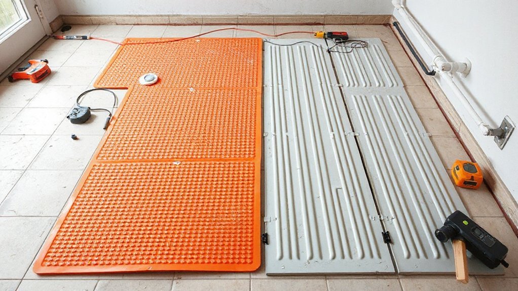
Before you buy materials, choose between electric underfloor heating (cable or mat) and hydronic (warm-water tubing) underfloor heating, because the system you pick drives the electrical, plumbing, and permit requirements.
Electric systems typically need a dedicated, GFCI-protected circuit, correct breaker sizing, and listed components installed per manufacturer instructions. You’ll schedule an electrical permit and rough/final inspections, and you must protect heating leads and splice points.
Hydronic systems add a heat source (boiler or water heater rated for space heating), pressure-rated tubing, mixing/limit protections, and backflow prevention where required. You’ll pull plumbing/mechanical permits and plan pressure testing before covering.
For energy efficiency, hydronic often pairs well with high-efficiency boilers, while electric suits small areas. Compare installation costs, timelines, and inspection scope.
Check Floor Type, Heat Load, and Controls (Thermostat/Sensor)
Even if you’ve already picked electric or hydronic, you still need to confirm your floor covering, calculate the room’s heat load, and specify the right thermostat and floor sensor, because these choices control allowable floor temperatures, required wattage/BTU output, and where you can legally and safely place heating elements or tubing.
Verify the manufacturer’s max surface temperature for tile, wood, vinyl, or carpet, and follow local code for wet areas and clearances.
Use a heat-loss/heat-load calc (room size, insulation levels, windows, infiltration) so you don’t undersize circuits or boiler output.
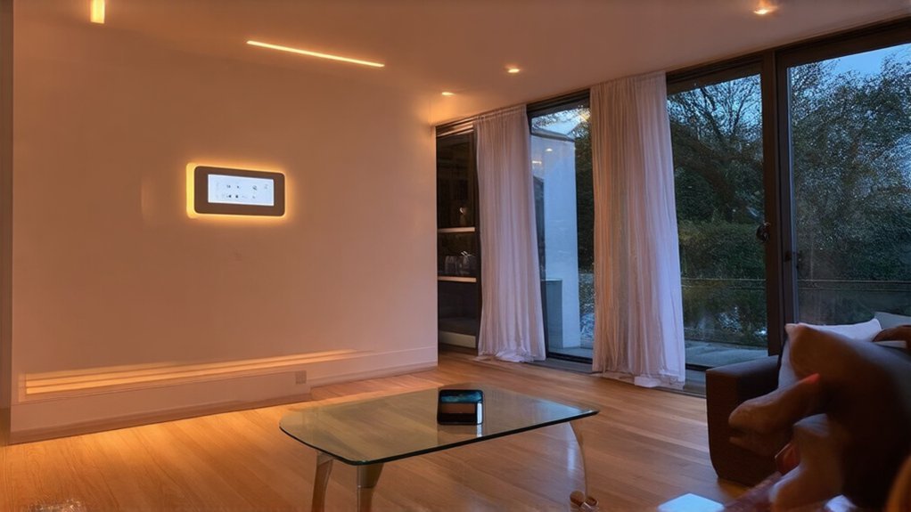
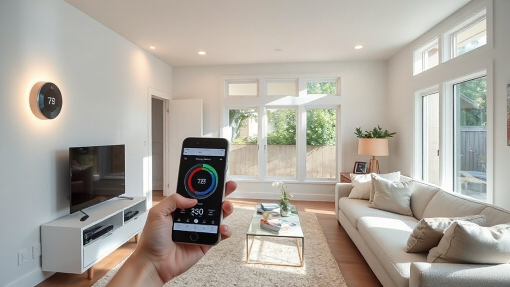
Choose a listed thermostat matched to voltage or zone valve/actuator type, and require Temperature sensors for floor-limiting and overheat protection.
Confirm Floor insulation R-values assumed in your load calc, and plan sensor routing away from power leads.
Prep the Subfloor: Level, Insulate, and Waterproof
Once you’ve confirmed the floor type, load, and controls, prep the subfloor so it’s flat, dry, stiff, and protected, because underfloor heating can’t compensate for dips, weak spots, or moisture problems.
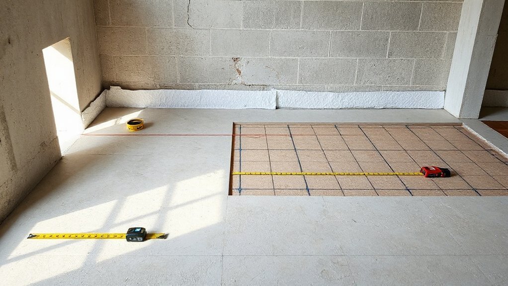
Start subfloor preparation by removing adhesives, paint, and debris, then vacuum and check for rot, delamination, or loose fasteners; re-screw per manufacturer spacing.
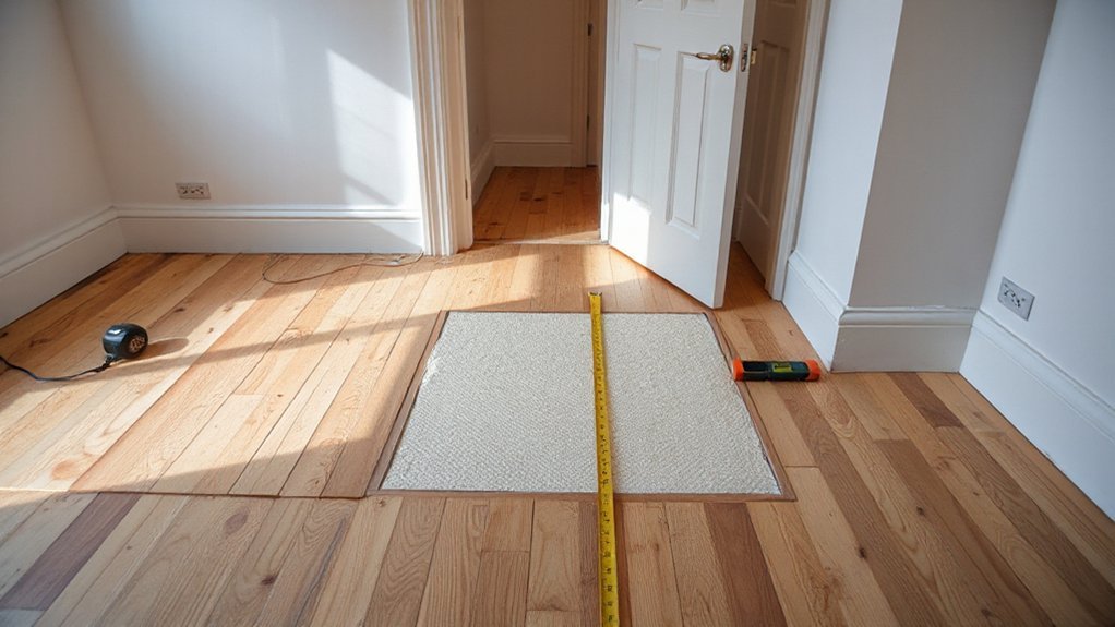
Verify flatness with a straightedge and correct low/high spots using a patching/leveling compound rated for the substrate. Keep deflection within tile or flooring requirements.
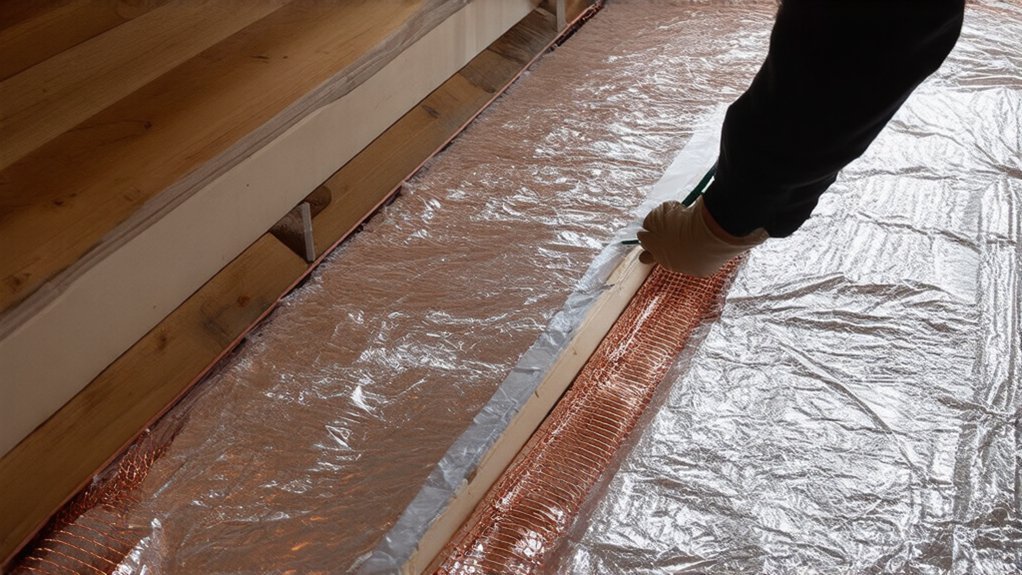
Add insulation boards or an insulating underlayment approved for the system to reduce downward heat loss and meet fire ratings.
Install moisture barriers appropriate to location (poly sheet, liquid membrane, or uncoupling layer), lap seams, tape, and seal penetrations. Let everything cure fully.
Install Electric Floor Heating Mats or Loose Cable
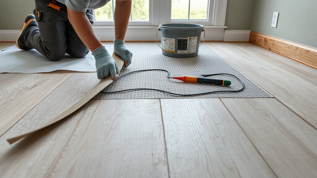
With the subfloor flat, insulated, and properly waterproofed, you can start laying the electric heating mat or routing loose cable according to the manufacturer’s plan and local electrical code.
Dry‑fit first, keep elements out of shower drains and under permanent cabinets, and maintain required edge clearances.
Never cut heating wire; only trim mesh backing.
Use approved adhesive or tape, and avoid crossing cables or creating tight bends that can overheat.
Route the cold leads to the electrical box, install conduit if specified, and place Smart sensors in a dedicated conduit between runs for serviceability.
Verify resistance and insulation values with a meter before, during, and after embedding.
Don’t energize until cured.
Connect to GFCI protection and compatible Wireless thermostats per listing.
Install Hydronic Radiant Floor Tubing and Manifold
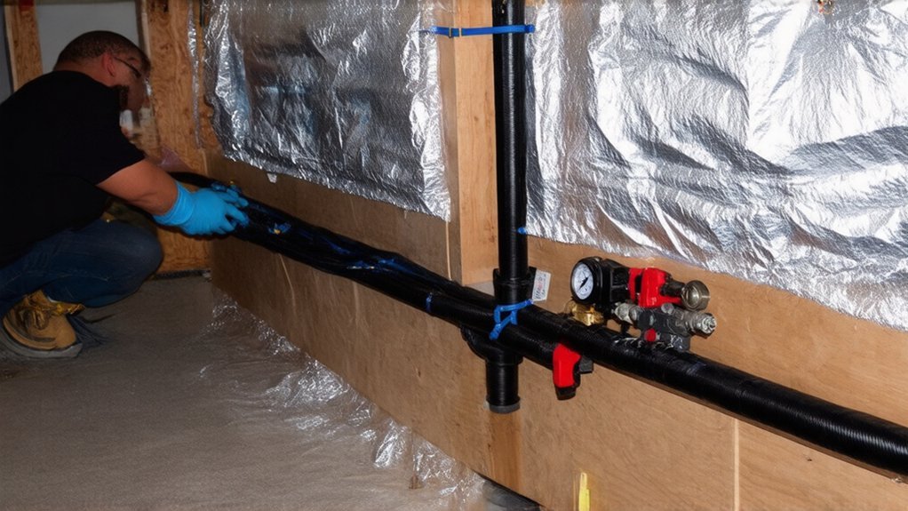
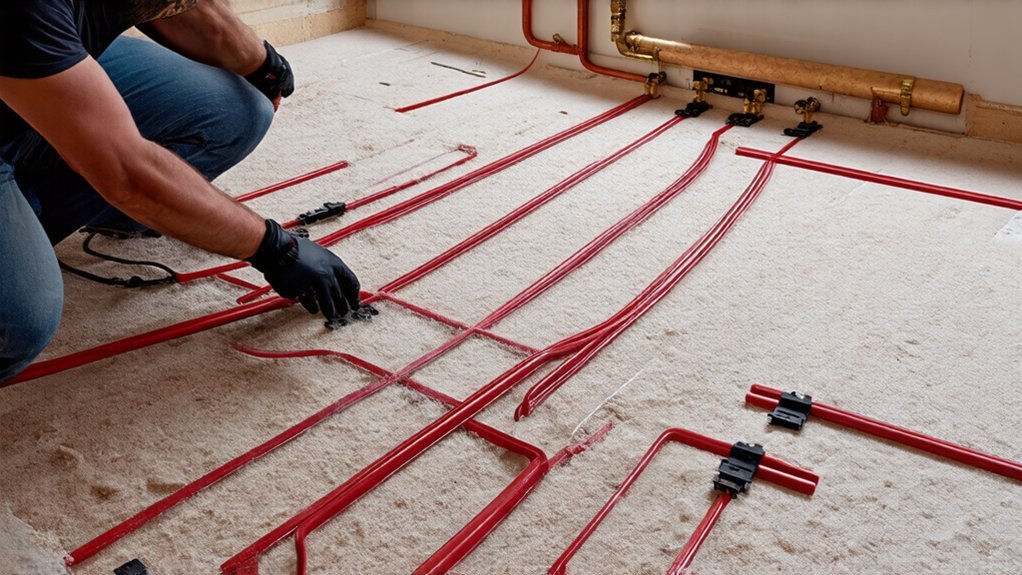
Plan your tubing layout and spacing per the manufacturer’s drawings and local code. Then secure the loops without kinks and maintain required clearances from walls and penetrations.
Mount the manifold in an accessible location at the specified height. Fasten it to solid framing, and label each circuit before you connect the supply/return lines.
Before you cover anything, pressure-test the system to the required PSI and duration. Then purge all air from each loop and verify there are no leaks.
Tubing Layout And Spacing
Before you uncoil a single loop, map your tubing layout and spacing to match the room’s heat load, floor assembly, and the manifold location so each circuit stays balanced and serviceable.
Choose a layout pattern—serpentine for simple zones, counterflow spiral for the most even surface temps—and keep supply runs at exterior walls and high-loss areas.
Maintain consistent tubing spacing (commonly 6–12 inches on center) and tighten it near glass or overhangs when calculations call for it.
Limit each circuit length per manufacturer tables to control head loss, and document every loop on an as-built sketch.
Use approved bend radii, don’t kink PEX, and protect tubing at penetrations with sleeves.
Keep tubing clear of fasteners, drains, and floor sensors.
Manifold Placement And Mounting
Because manifold location dictates loop lengths, balancing, and service access, mount it where you can reach the isolation valves, flow meters, air vent, and drain without moving equipment or opening finished walls.
For smart Manifold placement, choose an interior wall near the boiler or water heater, above flood level, and centered to keep supply and return runs short and similar.
Use a listed recessed cabinet or a solid backer fastened to studs or masonry anchors; don’t rely on drywall alone.
Apply proper Mounting techniques: keep the manifold level for accurate meters, maintain required clearances for covers, and isolate vibration with approved pads.
Install shutoffs on supply and return, label each loop, and protect penetrations with sleeves and firestop where required.
Support piping to prevent strain.
Pressure Test And Purge
Where do you catch a kinked tube, a loose compression fitting, or a mislabeled loop before it’s buried under insulation and concrete? During pressure testing. Cap the manifold outlets, connect a calibrated gauge, and pressurize with air or water per your tubing and local code.
Isolate each loop, verify labels, and hold test pressure for the specified duration; don’t allow any drop. Walk the runs, listen for leaks, and soap-check fittings. Keep the system pressurized while you pour or cover to prevent crushed tubing.
Next, complete system purging. Open one loop at a time, use a purge valve and fill cart or hose, and flush until flow is bubble-free. Close each loop, balance valves, then recheck pressure.
Test, Embed (Thinset/Screed), and Lay the Finished Floor
Before you cover anything, you’ll test the system for continuity/pressure and verify readings match the manufacturer’s specs and local code requirements.
Keep the heat source off while you embed the tubing or cables in approved thinset or screed at the specified thickness, and protect leads, sensors, and manifold connections from damage.
Once the embed layer cures, you’ll install the finished floor per the flooring manufacturer’s limits for radiant heat and document the test results before commissioning.
Test Heating Continuity
Once you’ve secured the heating cable or mat and routed the leads to the box, test continuity and insulation resistance to confirm the circuit matches the manufacturer’s ohm range and hasn’t been nicked during installation.
Lock out the circuit, then use a calibrated multimeter to record resistance across the heating leads and compare to the label; document results for inspection.
Next, use a megohmmeter at the specified voltage to verify insulation resistance to ground meets the maker’s minimum. If readings are out of tolerance, stop and troubleshoot before you energize anything.
Confirm the floor sensor reads within spec, and verify the equipment grounding conductor is continuous back to the panel.
When you’re ready for Smart thermostats, follow the wiring diagram to preserve Energy efficiency and GFCI protection requirements.
Embed System And Finish
With your continuity and insulation readings documented and in spec, you can embed the heating system and build the finished floor without risking hidden damage. Recheck readings before covering, then lock out power and protect the cold leads and sensor with listed conduit where required.
For tile, trowel polymer‑modified thinset and fully encapsulate the cable or mat without voids; keep trowel edges off conductors.
For floating floors or large areas, pour a level, manufacturer‑approved screed to the specified minimum cover, and don’t exceed maximum thickness that slows heat transfer.
Maintain required clearances from walls, drains, and penetrations for code‑safe system integration.
After cure, verify resistance again, then install your floor per rating for radiant heat.
Finish with trim, thermostat, and GFCI test for finishing touches.
Conclusion
You’re ready to close up the floor only after you’ve matched the system to your heat load, verified thermostat and sensor placement, and documented resistance/pressure test results. Prep and insulation matter: in-floor systems can cut space-heating energy use by up to 15% when properly installed and controlled—proof that details drive performance. Don’t bury cables or tubing until tests pass, cures meet manufacturer specs, and GFCI/overcurrent protection is confirmed. If anything’s unclear, you’ll call a licensed pro.…