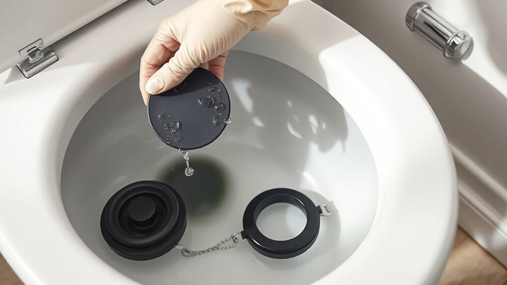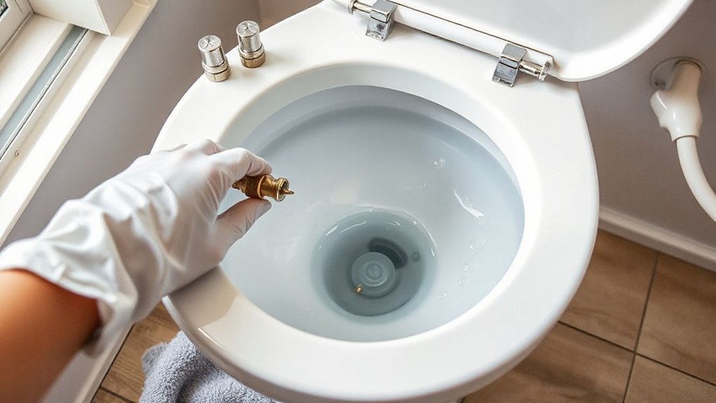

Plumbing & Electric Fixes

toilet keeps running fix
Plumbing & Electric Fixes

Fixing a Toilet That Keeps Running: Simple Repairs That Solve the Problem

Lift the tank lid and watch a full flush cycle, keeping hands clear of moving parts. Make sure the shutoff valve is fully open, then check that the water level stops about 1 inch below the overflow tube. If water spills into the tube, lower the float; if the tank refills by itself, run a dye test to confirm a leaking flapper. Clean mineral buildup on the seat, replace a warped flapper, and clip the refill hose above the overflow rim. Next, you’ll see how to fix stubborn fill valves and hidden tank leaks.

Key Takeaways

  • Watch a full flush cycle and use a dye test; color in the bowl after 10 minutes confirms a flapper/seat leak.
  • Set water level about 1 inch below the overflow tube rim; adjust the float so the fill valve shuts off cleanly.
  • Replace a warped or slimy flapper and clean mineral buildup on the flush valve seat; leave slight chain slack for full closure.
  • Ensure the refill hose clips above the overflow tube rim and the overflow tube is intact to prevent siphoning and constant refilling.
  • If the fill valve keeps running or parts are cracked/corroded after adjustments, replace the valve or call a plumber.

Diagnose Why Your Toilet Keeps Running

troubleshoot toilet running issue

Before you replace parts, pinpoint what’s keeping water moving: remove the tank lid carefully and watch a full flush cycle while keeping your hands clear of the flapper and linkage.

Confirm the shutoff valve is fully open, then listen: a steady hiss suggests refill flow; an intermittent run suggests a slow leak into the bowl.

Add a few drops of dye to the tank and wait 10 minutes without flushing; color in the bowl confirms a sealing issue.

Check that the flapper closes squarely and that the chain has slight slack, not tension.

Inspect the overflow tube for cracks or a loose refill clip.

If you’re doing Toilet seat replacement, don’t overtighten bolts.

Follow Bathroom cleaning tips: avoid in-tank tablets.

Open the Tank and Check the Water Level

Now that you’ve narrowed down whether the toilet’s running comes from refill flow or a slow leak, open the tank and verify the water level against the overflow tube.

Remove the Toilet tank lid carefully; porcelain chips easily. Set it on a towel so it won’t crack or slip. Don’t touch moving parts while the unit cycles.

With the tank full and the fill valve off, read the Water level: it should sit below the top of the overflow tube, typically about 1 inch.

If water stands at or above the tube’s rim, it can spill into the tube and run continuously.

If it’s far below normal, you may get weak flushes and repeated refills.

Note your observations before making any changes.

Adjust the Float to Stop a Running Toilet

Identify whether you’ve got a float cup on the fill valve or a float ball on an arm, because the adjustment method and setpoint differ.

With the water supply on and your hands clear of moving parts, adjust the float so the shutoff occurs with the waterline about 1 inch below the overflow tube (or at the manufacturer’s mark).

If the water still reaches the overflow, stop and recheck the fill valve and float linkage for binding or damage before you force any parts.

Identify Float Type

Once you’ve shut off the water and removed the tank lid, check what kind of float your fill valve uses, because the adjustment method depends on it and the wrong move can crack plastic parts or leave the valve out of calibration.

You’ll typically see one of two float types: a ball float on a long metal or plastic arm, or a cup (cylinder) float that rides up and down the fill-valve shaft.

A ball float usually connects to a lever with a screw or clip near the arm pivot.

A cup float usually has a pinch-clip, sliding collar, or small adjustment screw on the valve body.

Confirm the float moves freely without rubbing the tank wall or overflow tube, and note where the current water level sits before you touch anything.

Set Correct Water Level

After you’ve confirmed the float type and that it moves freely, set the tank’s water level to the manufacturer’s mark on the overflow tube (or about 1 inch below the top of the overflow tube if there’s no mark). Because a level that’s too high will spill into the tube and keep the toilet running.

Turn the supply shutoff clockwise, flush, then reopen slowly while you watch the refill.

For a float cup, pinch the clip and slide the cup down, or turn the adjustment screw.

For a ball float, bend the rod slightly down or turn its screw, depending on the model.

Use basic Plumbing tools only as needed, and don’t force plastic parts.

Recheck: water should stop below the tube and the fill valve should shut off cleanly. This supports Water conservation and prevents overflow.

Replace a Flapper That Won’t Seal

replace faulty flapper properly

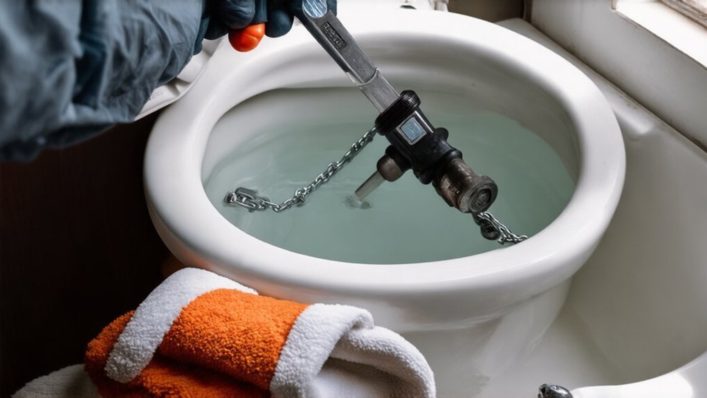
If the tank refills and you hear constant trickling into the bowl, you’ve likely got a flapper that won’t seal. Shut off the supply valve and flush to empty the tank before you inspect the seat and chain slack.

Unhook the chain, remove the old flapper from the overflow tube mounts, and clean any scale from the flush valve seat so the new seal meets code-grade performance.

Install the correct-size replacement, set minimal chain slack, turn the water back on, and test-flush to confirm the fill valve shuts off and the leak stops.

Diagnose Flapper Seal Issues

Two quick checks will tell you whether a leaking flapper is keeping your toilet running: remove the tank lid, flush, and watch the flapper as the tank refills— it should drop flat and stay seated without wobbling or drifting open.

Next, when the tank is full, add a few drops of food coloring; if color appears in the bowl without flushing, the seal’s leaking.

Shut off the stop valve if you need to reach into the tank, and don’t force brittle parts.

Inspect the flapper material for swelling, warping, or a tacky feel— all signs of seal deterioration.

Check the seat for mineral buildup or nicks that prevent full contact.

Confirm the chain has slight slack; a tight chain can hold the flapper open.

Remove Old Flapper

A failed food-coloring test or a flapper that won’t stay seated means it’s time to remove the old flapper so you can install a proper seal. Shut off the stop valve at the wall, then flush and hold the handle to drain the tank. Confirm the refill tube isn’t siphoning, and keep hands clear of sharp tank edges.

Disconnect the chain from the flush lever, noting the slack so you can diagnose misadjustment later. Unhook the flapper ears from the overflow-tube pegs, or slide off the ring-style flapper.

If mineral buildup is present, don’t pry against porcelain; wipe the seat and tube with a nonabrasive pad. Inspect Flapper materials for cracking, warping, or swelling that can affect toilet aesthetics and sealing. Dispose of the old part safely.

Install And Test Flapper

Now what seals that flush valve for good? Your new flapper.

With the water off and the Toilet tank drained to a low level, hook the flapper ears onto the overflow tube pegs. Align it so it sits flat on the valve seat with no twist.

Clip or thread the lift chain to the trip lever, leaving about 1/2 inch slack; too tight causes leaks, too loose prevents full opening.

Turn the supply back on and let the tank refill. Watch the seal line: you shouldn’t see ripples or hear hissing.

Add a few drops of dye; if color reaches the bowl without flushing, reseat or adjust.

This Flapper replacement must stop all seepage before you close up.

Set the Refill Tube and Overflow Height

Before you turn the water back on, set the refill tube so it clips securely to the overflow tube without sealing inside it, which helps prevent backflow and keeps the bowl refilling correctly.

In your Toilet tank, keep the refill tube above the overflow rim and use the clip, not a tight push-in fit.

Verify the overflow tube isn’t cracked and stands vertical.

Next, confirm the water level will sit below the overflow tube’s top, typically 1 inch, so the tank can’t siphon into the bowl.

If your overflow is adjustable, raise or lower it per the manufacturer’s marks and local code guidance.

Don’t cut it unless the instructions allow it.

Recheck that the flapper chain clears the tube and doesn’t snag.

Fix a Fill Valve That Won’t Shut Off

adjust float and valve

With the refill tube clipped correctly and the overflow height set, turn the supply back on and watch the fill valve: if water keeps running after the tank reaches its marked level (typically about 1 inch below the overflow rim) or you hear a steady hiss, the valve isn’t shutting off.

Shut the stop valve, flush to empty the tank, and sponge out remaining water for safe access.

Inspect the float for binding on the tank wall or rod; reposition it and verify smooth travel. Adjust the water level screw or clip per the manufacturer so shutoff occurs below the overflow rim for water conservation.

If the diaphragm/washer is gritty, remove the cap, rinse parts, and flush the supply briefly into a bucket. Replace the seal or the entire fill valve if worn to protect toilet aesthetics.

Stop Tank Leaks That Trigger Refilling

If the toilet shuts off briefly and then refills on its own, you’ve likely got a slow tank leak that lets the water level drop below the fill valve’s start point. Shut off the angle stop, flush, and verify the tank’s empty before you inspect.

Add a few drops of dye to the tank and wait 10 minutes; color in the bowl confirms a flapper or seat leak.

Clean mineral buildup from the flush valve seat, then replace the flapper if it’s warped, slimy, or stiff.

Check the overflow tube: the refill hose must clip above the tube’s rim to prevent siphoning.

Tighten tank-to-bowl bolts evenly and check for seepage.

This Toilet tank maintenance protects Bathroom plumbing and prevents ongoing refills.

Call a Plumber if the Toilet Still Runs

Although you can solve most running-toilet problems with a flapper or fill-valve adjustment, you should call a licensed plumber when the toilet still won’t shut off after those checks, since the issue may involve a cracked tank, a faulty flush-valve seat, or supply/valve problems that require code-compliant repair.

Shut off the stop valve, dry the tank, and look for hairline cracks, wobble at the flush valve, or corrosion at the supply line. If you see moisture at the handle shank or base, don’t overtighten parts; you can crack porcelain.

A plumber can pressure-test, replace the flush valve correctly, and verify backflow and shutoff performance. Professional documentation can protect Plumbing warranties, and proper repairs preserve Toilet aesthetics by preventing stains and mineral tracks.

Conclusion

If your toilet still runs, recheck each step: water level below the overflow, float moves freely, refill tube stays above the rim, and the flapper seals tight. Shut off the stop valve before swapping parts, and don’t overtighten plastic nuts. Example: after a “quick” flapper change, you notice constant refilling—turns out the refill tube was shoved into the overflow, creating a siphon. Correcting that stops the run and saves water.…

silence noisy plumbing issues
Plumbing & Electric Fixes

How to Stop Noisy Pipes: Causes and Quick Fixes

Match the sound to the cause, then fix it safely. If you hear banging after shutoff, you’ve got water hammer—check pressure (aim 40–80 psi), adjust/replace the PRV, and add listed hammer arrestors at quick-closing valves. Rattling means loose supports, so tighten or replace straps, add rubber isolators, and meet support spacing. Whistling points to high velocity or a failing stop/PRV—fully open stops, clean screens, and lower pressure. Gurgling signals venting or drain issues that may need code checks—there’s more to try next.

Key Takeaways

  • Identify the noise type: banging (water hammer), rattling (loose supports), whistling (valve/PRV issues), and gurgling (venting or drain blockage).
  • Check for loose straps or pipes touching framing; tighten clamps and add rubber/foam isolators to prevent vibration.
  • Verify fixture stops and appliance shutoffs are fully open; clean aerators, screens, and cartridges to remove debris causing turbulence.
  • Measure water pressure with a hose-bibb gauge; adjust or add a PRV to keep pressure about 40–80 psi (often 50–70 ideal).
  • Fix water hammer by adding hammer arrestors at quick-closing fixtures and consider an expansion tank if pressure spikes persist.

Identify the Noise: Banging, Rattling, Whistling, Gurgling

identify pipe noise causes

Before you reach for tools, you need to identify exactly what your pipes are “saying,” because each sound points to a different, code-relevant fault condition.

Banging usually indicates water hammer from fast-closing valves or inadequate support; note where it occurs and whether it follows fixture shutoff.

Rattling suggests loose pipe straps or contact with framing during flow changes, often violating support spacing requirements.

Whistling commonly tracks to a partially closed stop, failing pressure-reducing valve, or undersized supply creating excessive velocity.

Gurgling points to improper venting, partial drain obstruction, or trap siphonage, all drainage-code concerns.

Record which fixtures trigger it, hot vs. cold, and timing.

Also note condensation zones; Pipe insulation reduces thermal movement noise and supports corrosion prevention by limiting moisture.

Try These Quick, Safe Checks Before You Start

Since a “quick fix” can turn into a leak or shock hazard fast, start with a few noninvasive checks: confirm the noisy line isn’t contacting framing (look for scuff marks and loose straps), verify all fixture stops and appliance shutoffs sit fully open unless you’re deliberately throttling, and check for abnormal pressure by reading a hose-bibb gauge (most residential systems should run roughly 40–80 psi; higher pressure calls for PRV service).

Next, inspect exposed hot and cold runs for missing Pipe insulation where they pass through studs or rest on metal hangers; add listed insulation to reduce expansion noise and condensation.

Confirm escutcheons and trim plates aren’t binding the pipe.

Finally, if noise appears only at one fixture, clean aerators and showerheads and ensure supply hoses aren’t kinked.

Stop Banging Pipes: Fix Water Hammer Fast

If your quick checks look fine but you still hear a sharp bang when a valve or solenoid shuts off, you’re likely dealing with water hammer—an abrupt pressure spike that slams moving water against fittings and framing.

First, confirm your supply pressure meets code (typically 40–80 psi); if it’s high, install or adjust a pressure-reducing valve and add a thermal expansion tank where required.

Next, tame the water flow rate by partially closing fixture stop valves or adding a listed flow restrictor; slower velocity reduces the shock wave.

Install code-approved water hammer arrestors at fast-closing devices like dishwashers, washing machines, and ice makers, sizing per manufacturer specs.

Add Pipe insulation where pipes pass through studs to dampen impact noise without constricting movement.

Quiet Rattling Pipes by Securing Loose Straps

Track the rattle by inspecting exposed runs and locating loose pipe straps or hangers at studs, joists, and penetrations.

Bring the support up to code by tightening or replacing straps, then add approved cushioning (rubber isolators or sleeved clamps) to prevent pipe-to-framing contact.

Where movement persists, install properly sized pipe clamps/hangers at the required spacing and recheck for clearance and noise.

Locate Loose Pipe Straps

Where does that rattling actually come from? It’s usually a pipe shifting inside a loose strap or hanger when flow starts or stops.

Start by tracing the sound: run one fixture at a time and listen along exposed runs in basements, crawlspaces, and under sinks. Look for straps that let the pipe move, missing fasteners, or hangers pulled out of framing.

Confirm clearance at penetrations and avoid binding against joists or studs. For code-sound support, check that horizontal runs are supported at proper intervals and that straps aren’t corroded or deformed.

Note spots where pipe insulation is torn or missing; movement often abrades it. If pipe painting is planned, mark noisy locations first so you don’t hide suspect hardware.

Add Cushioning And Clamps

Once you’ve pinpointed the loose strap or hanger, stop the rattle by taking up the slack and isolating the pipe from hard surfaces. Slide cushioning foam or a rubber isolator between the pipe and framing, then re-seat the strap so it holds the pipe firmly without pinching.

Keep clearance from sharp edges and don’t compress insulation that’s required for condensation control. Replace bent straps with approved pipe clamps sized to the pipe’s OD, and fasten into solid wood or blocking with corrosion-resistant screws.

Space supports per code for the material (copper, CPVC, PEX), and add an extra clamp near elbows and valves. After tightening, run water and listen; adjust until vibration stops.

Fix Whistling Pipes by Lowering Water Pressure

If your pipes whistle when you open a faucet or flush a toilet, excessive water pressure often drives the vibration through valves and supply lines. Verify pressure with a hose-bibb gauge at an exterior spigot; many codes and manufacturers target 40–60 psi, and readings above 80 psi typically require correction.

If you have a pressure-reducing valve (PRV), shut off fixtures, loosen the locknut, and turn the adjustment screw counterclockwise to lower water pressure, then retest under flow.

If no PRV exists or it won’t hold setpoint, install or replace a listed PRV and add a thermal expansion tank where required by code on closed systems.

After you stabilize pressure, add pipe insulation where lines contact framing to damp residual whistle.

Stop Gurgling and Squeals: Bleed Air and Replace Washers

If you’re hearing gurgling or a sharp squeal, you’ll need to purge trapped air and verify the shutoff valves are fully open.

You can bleed the lines by shutting off the water, opening the highest and lowest fixtures to vent, then restoring service until flow runs steady.

If the squeal persists, you’ll replace worn faucet or toilet fill-valve washers with manufacturer-listed parts, reassemble to spec, and confirm the noise is gone under normal pressure.

Bleed Trapped Air

When air gets trapped in your water lines, it compresses and expands as fixtures cycle, which triggers gurgling, spitting, and high-pitched squeals. You can purge that air safely by bleeding the system from the highest fixture down, keeping control of water pressure.

Start by turning off the water heater (gas to “pilot” or electric breaker) to protect elements. Fully open the highest hot faucet, then open the highest cold faucet.

Next, open lower-level faucets one at a time, including tubs and outdoor hose bibbs, until flow runs steady with no spurts. Flush toilets last.

Keep the main shutoff fully open during bleeding to prevent partial-closure turbulence.

Restore normal settings, then recheck for vibration; add pipe insulation where lines contact framing.

Replace Worn Washers

Why do some faucets gurgle or squeal even after you’ve bled the lines? Worn faucet or stop-valve washers can flutter, leak, and induce turbulence that sounds like gurgling.

Shut off the fixture’s supply stops, open the faucet to relieve pressure, then disassemble the handle and stem. Replace the rubber washer and O-ring with matching parts, and inspect the seat for pitting; dress or replace it if needed.

Reassemble and restore water, then make small valve adjustments so stops are fully open, not throttled mid-way. Verify there’s no code-prohibited cross-connection or missing vacuum breaker on hose bibbs.

Afterward, add pipe insulation on nearby runs to reduce vibration transfer. Test flow at hot and cold.

Silence High-Pitched Squeals

Although you’ve already bled the lines and swapped worn washers, a high-pitched squeal usually points to a restriction that’s driving water to cavitate or a valve component that’s still chattering under pressure. Verify the stop valve is fully open, then inspect angle stops, aerators, and cartridges for debris; flush screens and replace cartridges that vibrate.

If you’ve got a pressure-reducing valve, confirm it’s correctly set (typically 50–70 psi) and replace it if it hunts. Add listed water-hammer arrestors at quick-closing fixtures per code and secure loose supply lines with approved clamps, keeping required clearances from electrical.

Wrap exposed runs with pipe insulation to damp resonance, then line access panels with soundproofing materials rated for moisture and fire.

Conclusion

Noisy pipes aren’t “just old house charm”—they’re a warning flag. Think of it like a server log: one odd entry is easy to ignore until the system crashes. One homeowner I worked with chased a midnight bang for weeks; a $12 water-hammer arrestor dropped the spike from ~80 psi to 55 psi and the noise stopped. You’ll get faster results by identifying the sound, securing straps, setting pressure to code, bleeding air, and swapping worn washers.…

electrical switch replacement guide
Plumbing & Electric Fixes

Replacing a Faulty Light Switch: Safe and Simple Electrical Steps

If your switch flickers, feels gritty, runs warm, crackles, or shows discoloration, replace it with a like‑for‑like unit (single‑pole has 2 brass screws; 3‑way has a common plus 2 travelers). Shut off the correct breaker, then prove the circuit is dead with a voltage tester on all conductors. Remove the plate, pull the switch out, label line/load/ground, reconnect tightly, reassemble, restore power, and test; keep going for extra tips.

Key Takeaways

  • Confirm the switch is faulty by checking flickering, heat, arcing sounds, loose mounting, or burning smell before replacing it.
  • Identify the switch type (single-pole or 3-way) by terminal count and labels; don’t rely on wire colors alone.
  • Turn off the correct breaker and verify all wires are de-energized using a voltage tester before touching conductors.
  • Label and disconnect wires carefully, inspect for damage, and match the replacement switch’s voltage/amperage and terminal style to the original.
  • Reconnect hot, load, and ground securely, mount the switch flush, reinstall the cover, restore power, and test for normal operation without arcing.

Spot the Signs You Need to Replace a Light Switch

signs of faulty light switch

Although many switch problems look minor at first, you should replace a light switch if it shows clear failure or heat damage: intermittent operation (lights flicker when the toggle is steady), arcing or crackling sounds, visible discoloration or melting on the device or cover plate, a loose yoke that won’t tighten securely in the box, or a warm faceplate under normal load.

You should also act if the switch feels gritty, binds, won’t latch positively, or if the lights stay on/off inconsistently, indicating worn contacts. If you smell burning insulation, see soot at the strap, or find brittle conductors when you remove the cover plate, stop and de-energize at the breaker.

A failing switch can undermine Lighting design by causing nuisance flicker and can reduce Energy efficiency through poor contact resistance and heat. Replace with a listed device of correct rating.

Identify Your Switch Type (Single-Pole vs. 3-Way)

Once you’ve decided the switch really is failing, identify whether you’re dealing with a single-pole or a 3-way before you buy parts or move any conductors.

A single-pole controls a light from one location and typically has two brass terminal screws plus a green ground.

A 3-way controls the same load from two locations and has three current-carrying terminals: one common (often a dark screw) and two travelers (brass), plus ground; it won’t have ON/OFF markings.

Confirm by removing the cover plate and looking for a 3-conductor cable (often red/black/white) on a 3-way.

Don’t rely on wire colors alone—verify with wiring diagrams and terminal labeling for switch compatibility and correct conductor placement.

If anything looks nonstandard, stop.

Grab the Tools and the Correct Replacement Switch

Before you shut off any power, gather what you’ll need and buy a switch that matches the exact function and ratings of the original: single-pole or 3-way, the same voltage (typically 120/277V), and an amperage rating at least equal to the circuit (most commonly 15A or 20A).

Check switch compatibility by matching terminal style (screw, backwire clamp), grounding provision, and whether you need a neutral for smart controls.

If you’re replacing a dimmer, confirm it’s rated for the lamp type (LED/CFL/incandescent) and total wattage.

For tool organization, lay out an insulated screwdriver set, wire stripper, needle-nose pliers, non-contact voltage tester, flashlight, and a small parts cup for screws.

Bring a UL/CSA-listed cover plate if the old one’s cracked.

Turn Off the Breaker for the Light Switch Circuit

At your service panel, identify the correct circuit breaker feeding the light switch by using the panel directory and confirming by turning the switch load on/off.

Move that breaker fully to OFF to de-energize the circuit, and don’t rely on the wall switch for isolation.

Verify the switch is dead at the box with a properly rated voltage tester on all conductors to ground and neutral before you touch any wiring.

Identify Correct Circuit Breaker

How do you make sure you’ve killed power to the switch you’re replacing? Start at your service panel and use the directory label as a guide, but don’t trust it blindly. For circuit safety, you’ll confirm the branch circuit by testing, not guessing.

Turn the light on, then have a helper toggle breakers one at a time while you note which breaker controls that load. If the light is fed by a multi-location setup, check every related switch position to confirm consistent control.

Re-label the panel directory immediately using clear room and load descriptions so it matches Electrical codes expectations for identification. If breakers aren’t labeled or multiple rooms go dead, stop and map the circuit before proceeding.

Never assume “off” equals de-energized.

Shut Off Breaker Power

Keep the panel cover closed, stand to the side, and use one hand when operating the handle to reduce shock exposure.

Don’t rely on wall switches, dimmers, or smart controls to de-energize conductors; only the breaker provides the required disconnect.

Set out your Switch installation tools now—insulated screwdriver, wire strippers, and a listed replacement device—so you won’t leave the work area.

Planning ahead also protects Lighting aesthetics by preventing rushed, misaligned hardware.

Verify Switch Is Dead

With the breaker switched off and your tools within reach, prove the circuit is actually de-energized before you touch any conductors. Flip the wall switch on, then try the light; it should stay dark. Don’t rely on the lamp alone—use a non-contact voltage tester at the switch yoke and at each insulated conductor in the box.

Next, pull the switch out slightly and use a two-pole tester or multimeter: test hot-to-neutral and hot-to-ground; you should read 0 volts. Confirm your tester works by checking a known live receptacle before and after.

Follow wire color coding (black/red hot, white neutral, green/bare ground), but still test—miswires happen. These checks align with electrical code standards and reduce shock risk.

Verify Power Is Off With a Voltage Tester

Before you touch any conductors, confirm the circuit is de-energized using a properly rated voltage tester. For electrical safety, use a CAT III (or better) tester and verify it works on a known live source first.

Then test the switch box: place one probe on the suspected hot and the other on neutral or the equipment grounding conductor. You should read 0 V.

Test hot-to-ground and hot-to-neutral, because an open neutral can mislead you.

If you’re using a non-contact tester, treat it as a screening tool only and confirm with a contact meter.

Re-check the live source afterward to prove the tester didn’t fail.

This voltage testing sequence meets safe work practice expectations and reduces shock risk.

Remove the Old Switch and Label the Wires

With power confirmed off, remove the wall plate, then loosen the mounting screws and pull the switch straight out to expose the terminals.

Before you loosen any terminal screws or wire connectors, label each conductor with tape (line/hot, load/switched hot, neutral if present, and ground) to preserve the correct connections.

Keep the wires separated and supported so they can’t touch the metal box or each other while you work.

Unscrew And Remove Switch

Once you’ve confirmed the circuit is de-energized, how do you remove the old switch without losing track of the wiring? Start by removing the cover plate screw, then back out the two mounting screws securing the switch to the box. Pull the device straight out a few inches, keeping conductors undisturbed to maintain wiring safety. Don’t force it; if it binds, check for paint, drywall pressure, or a misaligned yoke.

With the switch exposed, inspect the box fill and grounding path. Confirm the device type (single-pole, 3-way, 4-way) and verify switch compatibility with your replacement. If you see brittle insulation, overheated terminals, or a damaged strap, stop and correct the issue before proceeding.

Keep the switch supported so wires aren’t strained.

Label Wires Before Disconnecting

Even though the switch wiring may look straightforward, you’ll save time and prevent miswires by labeling every conductor before you loosen a single terminal. With power confirmed off, take a clear photo, then apply tape flags and write “LINE,” “LOAD,” “TRAVELER,” and “GROUND” as applicable.

Don’t rely only on wire color codes; repainting, age, or prior repairs can defeat expectations. Identify the common on 3-way/4-way switches and mark it distinctly.

Next, loosen terminal screws and pull each conductor free using insulated tools, keeping bends gentle to avoid nicking copper. Cap any loose hot candidates with a wire connector until you’re ready to reconnect.

Proper labels also verify switch compatibility, ensuring you reinstall the correct single-pole, 3-way, or smart-rated device.

Connect the New Light Switch, Then Test It Safely

After you’ve confirmed the circuit is de-energized at the box with a non-contact tester, connect the new switch to match the original wiring: land the hot feed and switched-hot on the switch’s brass terminals (or the two leads on a standard single-pole).

Bond the bare/green equipment ground to the green screw and the metal box if present, and keep all splices tight under listed wire connectors. Use color coding and verify wire insulation is intact; re-strip to clean copper if nicked.

Fold conductors neatly, keep grounding continuous, and mount the switch with the yoke flush to the box. Install the cover plate.

Restore the breaker, then test with the switch in both positions and confirm the fixture operates normally. If it trips or arcs, shut off power and recheck connections.

Conclusion

You’ve spotted the warning signs, identified whether you’ve got a single-pole or 3-way switch, gathered the right tools, and shut off the correct breaker. You’ve verified de-energized conductors with a voltage tester before touching anything. After labeling and transferring each wire to the matching terminal, you’ve tightened connections to manufacturer torque and reinstalled the device and cover. Restore power and test operation. Follow these steps, and you’ll feel a million times safer working in the box.…

fixing a clogged sink
Plumbing & Electric Fixes

How to Repair a Slow‑Draining Sink Without Calling a Plumber

Start by timing drainage: run water 30 seconds, stop, and watch drawdown; instant backup points to the stopper, strainer, or trap, while gradual slowing suggests a branch drain or vent issue. Flush with hot water 2–3 minutes, then dump a full basin. Plunge with the overflow sealed, or use a wet/dry vac to pulse suction. Remove and scrub the stopper, then clean the P-trap and reassemble leak-free. If it’s still slow, hand-snake the wall stub-out to clear deeper clogs—and there’s more help ahead.

Key Takeaways

  • Diagnose the slowdown by timing drawdown after a 30‑second run; early backup indicates trap/strainer issues, later slowdown suggests branch or vent problems.
  • Flush with hot water 2–3 minutes, then dump a full basin to scour grease and loosen soft buildup.
  • Plunge effectively by sealing the overflow, adding enough water to cover the bell, and pumping 10–15 strong strokes.
  • Remove and clean the stopper and drain opening using a plastic drain tool, then scrub with detergent and rinse hot.
  • Disassemble and clean the P‑trap, or snake through the wall stub‑out for deeper clogs; avoid caustic chemicals and leak‑test afterward.

Find Where the Slow‑Draining Sink Clog Is

identify sink clog location

Before you start disassembling anything, pinpoint where the restriction is by checking how the sink drains under controlled conditions. Run water at a fixed flow rate for 30 seconds, then stop and time the drawdown.

If the bowl backs up immediately, suspect the tailpiece, strainer, or trap arm. If it slows after initial flow, suspect the branch drain or venting.

Shut off power to any nearby receptacles and use PPE. Perform Pipe inspection by verifying the trap weir isn’t siphoning and the trap arm has proper slope.

Use Drain visualization with a flashlight and mirror through the stopper opening, and note gurgling, oscillating water level, or sewer odor, which indicates a partial blockage or vent restriction upstream.

Try Fast Fixes for a Slow‑Draining Sink

Now that you’ve narrowed down where the restriction likely sits, start with fast, low‑risk fixes that don’t require opening the drain. Run hot water for 2–3 minutes to soften grease, then flush with a full basin dump to increase hydraulic scouring.

Next, use a cup plunger: seal the overflow with a damp rag, add enough water to cover the bell, and pump 10–15 strokes to create pressure oscillation.

If you have a wet/dry vacuum among your DIY tools, switch to wet mode, seal the hose at the drain with a towel, and pulse suction.

Avoid caustic chemicals that can damage piping and violate local code guidance. Add these steps to your maintenance schedule to prevent recurrence.

Clean the Stopper and Drain Opening (Hair/Soap)

If the sink still drains slowly, the stopper and drain throat often hold a compacted plug of hair, soap scum, and toothpaste that restricts flow. Put on nitrile gloves and eye protection, then close the faucet and remove standing water with a cup.

Release the stopper: for a lift‑rod type, loosen the clevis strap pivot linkage and lift the stopper out; for a pop‑up, twist and pull per the manufacturer’s design. Use a plastic drain tool or hemostat to extract debris from the drain opening without scratching the finish.

Scrub the stopper with a nylon brush and mild detergent; don’t use caustic chemicals. Rinse hot, reinstall, and test.

This Drain cleaning step improves Stopper maintenance and restores flow.

Clear the P‑Trap Under the Sink (and Reassemble)

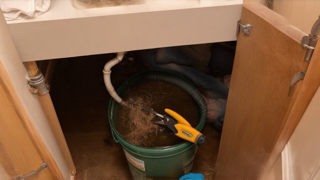
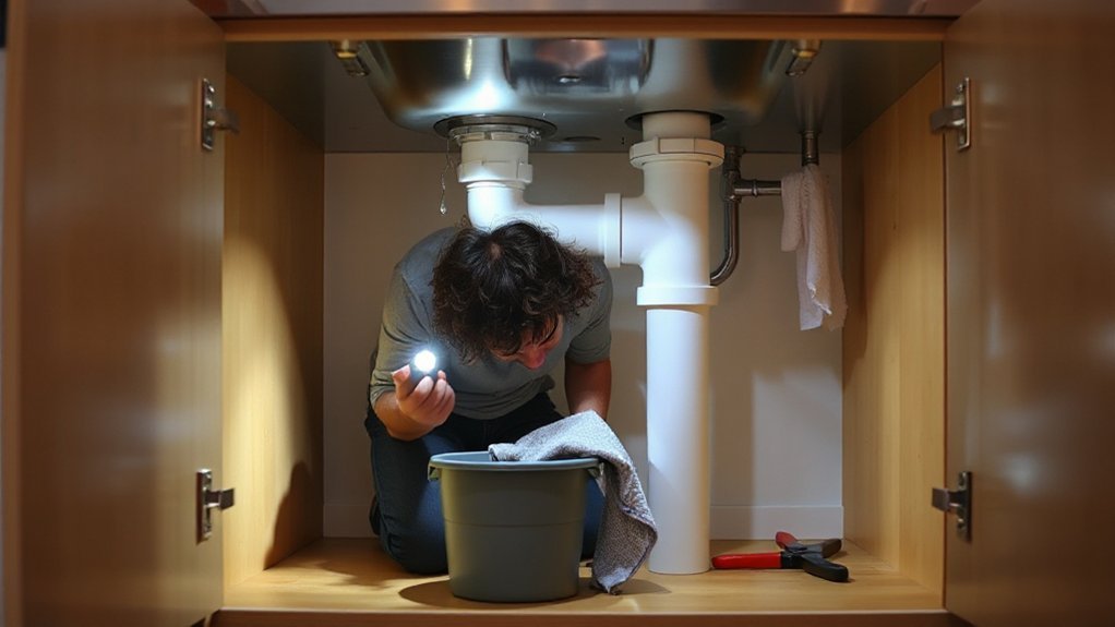
When debris slips past the drain opening, it often settles in the P‑trap—the U‑shaped fitting under the sink that holds a water seal and can clog with soap scum and grit. Place a bucket under it, put on gloves, and ventilate the cabinet area. Close the stop valves if you’ll disturb the supply lines.

Loosen the slip nuts by hand or with tongue‑and‑groove pliers, supporting the trap arm to prevent strain on the trap adapter. Lower the trap, drain it, and remove buildup with a bottle brush; flush the parts with hot water.

For pipe maintenance, verify the beveled washers face the correct direction and the trap weir aligns without cross‑threading. Reassemble finger‑tight, then snug 1/4 turn. Run water and perform leak inspection at every joint.

Snake the Drain for Deep Clogs (Then Prevent Repeats)

A clean, properly reassembled P‑trap that still drains slowly points to a clog farther down the branch drain, and a hand auger (drain snake) clears it mechanically without relying on caustic chemicals. Place a bucket, wear gloves and eye protection, and remove the trap arm to access the wall stub-out.

Feed the cable into the branch, rotate clockwise, and advance until you feel resistance. Work the head through the obstruction with short push-pull strokes, then retract while rotating to capture debris. Restore the slip-joint washers, tighten hand-tight plus a quarter turn, and leak-test.

For drain maintenance and clog prevention, flush hot water weekly, use a strainer, keep grease and coffee grounds out, and enzyme-treat monthly.

Conclusion

You’ve traced the restriction, tried quick clears, cleaned the stopper, serviced the P-trap, and snaked the branch drain, so your sink should discharge freely. Verify flow with hot water and check every slip-joint for leaks; tighten hand-snug plus a quarter turn, not over-torqued. If you used chemicals, flush per label and ventilate. Treat the drain like a highway after an accident—keep debris out. Use a screen, avoid grease, and rinse routinely.…

electrical issues causing flickering
Plumbing & Electric Fixes

Troubleshooting Flickering Lights: Common Electrical Issues and Easy Fixes

If your lights flicker, treat it as a warning sign and check the scope first: one bulb, one room, or the whole house. Tighten or replace a loose bulb, confirm the wattage matches the fixture, and make sure your LED works with the dimmer. Reset a tripped breaker once, then stop if it trips again. Run large appliances separately to spot overloads. If you notice heat, burning odor, buzzing, sizzling, or discoloration, shut off power and call an electrician—next you’ll see the most common causes and fixes.

Key Takeaways

  • Treat repeated or worsening flicker, heat, burning odors, buzzing, or discoloration as hazards; shut off power and call an electrician.
  • Identify scope: one bulb, one room, or whole house; broader flicker often indicates circuit overloads or utility/service connection problems.
  • Check bulb and fixture compatibility, correct wattage, and LED/CFL dimmer suitability; incompatible dimmers commonly cause flicker or ghost glow.
  • Inspect and tighten loose bulbs, and replace worn or scorched sockets; flicker when touched or wobbling bulbs suggests poor contact or arcing.
  • Reset tripped breakers once and observe load-related flicker; repeated trips, hot panels, or failure to reset require professional diagnosis.

Are Flickering Lights Dangerous? Key Warning Signs

detect and address flickering hazards

Although a brief flicker can come from a loose bulb or a momentary utility dip, you should treat repeated or worsening flickering as a potential electrical hazard until you’ve ruled out a code-compliant cause.

If you notice heat, a burning odor, buzzing, sizzling, or discoloration at switches, fixtures, or panel covers, shut the circuit off and call a licensed electrician.

Don’t ignore frequent dimming that coincides with motor starts, or lights that surge unusually bright; both can signal loose terminations, overloaded conductors, or failing devices.

If a breaker trips, won’t reset, or feels hot, stop troubleshooting.

You’ll protect lighting aesthetics, improve energy efficiency, and reduce fire risk by prioritizing safe diagnostics and proper torque, splicing, and grounding.

Is It One Bulb, One Room, or the Whole House?

Once you’ve ruled out obvious danger signs, narrow the problem by mapping the flicker’s scope: one bulb, one room/circuit, or the whole house. If it’s isolated to a single lamp or Decorative fixtures, suspect the fixture, socket, or driver compatibility; Lighting aesthetics upgrades often introduce dimmers, LEDs, and controls that don’t always play nicely together.

If multiple lights in one room flicker, track what’s on that circuit and whether switching loads correlates, which can indicate a localized connection issue or an overloaded branch circuit requiring professional evaluation.

If the entire house flickers—including receptacle-connected lamps—think service-level problems: utility voltage fluctuation, meter base issues, or a failing main connection. Document when it happens, what’s running, and call a licensed electrician or your utility.

Quick Fixes: Bulb Fit, Breaker Reset, and Load Checks

Before you start chasing wiring faults, you can rule out a lot of harmless flicker with three safe checks.

First, confirm the lamp or fixture is rated for the bulb type and wattage you’re using, then verify any dimmer is LED/CFL-compatible and properly rated. If you use Smart lighting, update the app/firmware and disable aggressive “adaptive” features that can pulse output.

Second, check your panel for a tripped breaker. Stand on a dry surface, look for a handle between ON and OFF, and reset it fully OFF then ON. If it trips again, stop and call a licensed electrician.

Third, do a load check: run large appliances one at a time and note flicker. Managing simultaneous loads improves energy efficiency.

Loose Bulbs and Worn Sockets That Cause Flicker

If your light flickers when you touch the lamp or tap the fixture, you’re likely dealing with a loose bulb or a socket that’s worn and not maintaining solid contact.

You should confirm the symptom with power off, inspect for heat damage or corrosion, and stop using the fixture if you see arcing, discoloration, or a loose center tab.

When replacement is needed, you’ll shut off the correct breaker, verify de-energization, and swap the socket or fixture with a properly rated, code-compliant part.

Signs Of Loose Bulbs

A loose bulb or a worn socket is one of the most common, code-relevant causes of flickering because it creates an intermittent connection that can arc and overheat. You’ll often notice quick, irregular flashes when the lamp is bumped, a bulb that wobbles, or light that cuts out then returns.

Watch for dark scorch marks on the bulb base, a hot-to-the-touch socket shell, or a faint buzzing. These are warning signs, not “lighting aesthetics” issues, and they can shorten bulb lifespan.

Before touching anything, switch off the breaker and let the bulb cool. If the bulb wasn’t fully seated, tighten it gently—no forcing.

If flicker persists, stop using that fixture and schedule service.

Diagnosing Worn Sockets

Once you’ve ruled out a bulb that simply wasn’t seated, focus on the socket itself—worn contacts and heat-damaged insulation can’t hold a solid connection and will keep producing intermittent flicker and arcing.

Turn off the breaker, verify power is off with a non-contact tester, and let the lamp cool.

Inspect the shell and center contact: pitting, dark spots, melted phenolic, or a springy tab that doesn’t press firmly indicate a worn socket.

Look for contact corrosion (green/white buildup) that increases resistance and heat.

Gently wiggle the bulb base; any play suggests poor tension.

If flicker changes when you tap the fixture or move the cord, suspect internal loosening.

Stop using the circuit if you smell burning.

Safe Replacement Steps

Before you replace anything, lock in a safe, code-compliant work setup: switch off the correct breaker (not just the wall switch). Verify the fixture is de-energized with a non-contact tester and a meter when accessible, and let the lamp or socket cool fully.

Tighten a loose bulb to snug—don’t over-torque—or swap in a known-good lamp to confirm the flicker follows the bulb. If the socket feels sloppy, shows heat marks, or won’t grip the base, replace the lampholder.

Use Electrical safety basics: insulated gloves as needed, eye protection, and a stable ladder.

Gather Replacement tools: screwdriver, wire stripper, needle-nose pliers, and approved wire connectors.

Match wattage, base type, and fixture rating, then restore power and recheck for flicker.

Switches, Dimmers, and LED Compatibility Issues

Although your wiring may be fine, a mismatched switch or dimmer often triggers LED flicker, strobing, or a faint “ghost” glow—especially when the fixture is on a dimmer.

First, confirm Dimmer compatibility: check the dimmer’s LED/CFL rating, minimum load, and approved bulb list, then match it to your lamp wattage and driver type.

If you’ve installed smart switches, verify they don’t require a neutral in that box before energizing.

Next, inspect switch wiring with power off at the breaker: make sure line and load aren’t reversed, terminals are tight, and any multi-way setup uses the correct dimmer model.

If flicker persists, replace the dimmer with a listed LED-rated unit and retest at full brightness.

Circuit Overloads and Wiring Faults Behind Recurring Flicker

If your lights still flicker after you’ve ruled out bulb and dimmer issues, the circuit itself may be dipping voltage under load or suffering from a loose, damaged, or miswired connection.

Start by noting what else runs when the flicker appears: heaters, microwaves, and compressors can push circuit capacity past safe limits. If flicker tracks these starts, redistribute loads or add a dedicated circuit—don’t upsize a breaker without matching wire gauge per code.

Next, inspect for wiring integrity problems: loose neutrals, backstabbed receptacles, worn switches, or overheated splices can arc and cause intermittent drops. Shut off power, verify de-energized, and tighten terminations to torque specs.

Call a licensed electrician if you find scorching, aluminum wiring, or repeated breaker trips.

Conclusion

Flickering lights aren’t just pesky—they can signal serious, system-wide stress. Start simple: snug the bulb, swap a suspect socket, reset a tripped breaker, and spread heavy loads. Then scrutinize switches and dimmers for LED compatibility. If the flicker follows a circuit, treat it as a wiring warning: loose lugs, failing neutrals, or overloaded conductors. Stay safety-first and code-compliant—shut power off, verify with a tester, and call a licensed electrician when in doubt.…

improve bathroom kitchen water pressure
Plumbing & Electric Fixes

How to Fix Low Water Pressure in Bathrooms and Kitchens

Check whether low pressure hits one fixture or the whole house by testing hot and cold at several taps, then confirm with a hose-bibb gauge (aim 40–60 psi). If it’s isolated, remove and clean the faucet aerator or showerhead screen with vinegar and flush debris. For tub/showers, strong tub flow but weak shower points to a worn diverter. If it’s everywhere, verify valves are fully open, inspect supply lines, and check the PRV. More steps follow.

Key Takeaways

  • Test hot and cold at several fixtures to see if low pressure is localized or affects the whole house.
  • Measure static and running pressure with a hose-bibb gauge; aim for 40–60 psi and note drops under flow.
  • Fully open main shutoff, meter valve, and under-sink angle stops; replace kinked or collapsed supply lines.
  • Clean or replace faucet aerators and showerhead screens by removing debris and soaking parts in white vinegar.
  • If pressure is low everywhere, check/adjust the PRV and look for leaks using the water meter; call a plumber for hidden leaks.

Diagnose Low Water Pressure: One Fixture or Whole House

check entire plumbing system

Before you start adjusting valves or swapping parts, confirm whether the pressure drop affects one fixture or the whole house. Check both hot and cold at several taps, then compare showers, kitchen, and outdoor hose bibbs to isolate zones.

For Water pressure testing, thread a gauge onto a hose bibb or laundry tap and record static pressure, then open a fixture to note dynamic pressure. Most homes target 40–60 psi per common code guidance.

If readings are low everywhere, verify the main shutoff and meter valve are fully open and look for recent utility work.

If pressure is normal at the gauge but weak at distant branches, prioritize Pipe corrosion detection: inspect exposed galvanized runs, discoloration, pinhole leaks, or debris at shutoffs.

Fix Low Water Pressure at Faucets (Aerators & Buildup)

Once you’ve confirmed the pressure drop shows up at a specific faucet rather than the whole house, start with the simplest restriction point: the aerator or faucet outlet.

Shut off the faucet, close the drain, and use padded pliers to remove the aerator without damaging the finish. Inspect the screen for debris and mineral buildup; note whether flow improves with the aerator removed (briefly run water to test, controlling splash).

Perform aerator cleaning by soaking parts in white vinegar, then brushing and rinsing. Replace cracked screens or missing O-rings to prevent leaks.

If the faucet has a concealed outlet, follow the manufacturer’s instructions and don’t exceed torque.

Restore service, verify steady flow on hot and cold, and recheck for drips.

Fix Low Water Pressure in the Shower (Head, Restrictor, Diverter)

If the low pressure shows up mainly in the shower, isolate whether the restriction sits at the showerhead, the flow restrictor, or the tub/shower diverter.

Start by turning off the shower, then cover the drain so small parts can’t fall in. Unscrew the shower head and check the inlet screen for grit or scale; flush it and soak parts in vinegar if allowed by the manufacturer.

If spray is still weak, look for flow restrictors inside the head or connector; remove only if your local code permits, since many jurisdictions require them for water efficiency.

For tub/shower combos, run the tub spout: strong tub flow but weak shower points to a worn diverter. Replace the diverter assembly or spout per listed parts.

Check Shutoff Valves, Supply Lines, and the Pressure Regulator

Low pressure that isn’t confined to a single fixture usually traces back to a partially closed shutoff, a kinked or clogged supply line, or a misadjusted pressure-reducing valve (PRV).

Start with Valve maintenance: confirm the main valve and all branch shutoffs are fully open, then check under-sink angle stops for seized stems or debris. Inspect braided connectors for sharp bends, crushing, or internal liner collapse, and replace any damaged line with the correct rated length and washers.

Next, do Pressure testing with a threaded gauge at a hose bibb or laundry tap; most systems should read roughly 40–80 psi. If pressure is low everywhere, inspect the PRV direction arrow and screen, then adjust per manufacturer instructions, in small increments, without exceeding code limits.

Find Hidden Leaks and Know When to Call a Plumber

Because a concealed leak can mimic system-wide pressure loss, you should rule it out before you keep adjusting valves or the PRV.

Start with Leak detection: shut off all fixtures, then watch the water meter; if the dial moves, you’ve got flow somewhere. Check under sinks, behind toilets, at the water heater, and along exposed piping for corrosion, staining, or damp insulation. Listen for hissing in walls and note warm spots on slabs.

Don’t ignore a running toilet; it can drop pressure at other taps.

For Plumbing maintenance, replace failed supply lines and repair dripping stop valves promptly.

Call a licensed plumber if you suspect a slab leak, hidden piping failure, gas water heater issues, or any code-required repairs.

Conclusion

Low water pressure won’t fix itself, but you can. You diagnose whether it’s one fixture or the whole house, you clean aerators and flush buildup, you service the showerhead, restrictor, and diverter, and you confirm shutoffs, supply lines, and the pressure regulator are fully open and set within code. You listen for leaks, you watch the meter, you document changes. If pressure stays unsafe or pipes show damage, you call a licensed plumber.…

hallway radiator installation guide
Plumbing & Electric Fixes

Installing a Radiator in a Hallway: Positioning, Pipework and Heat Efficiency

Before you add a hallway radiator, you should confirm the space is truly cold, not just draughty, and check your boiler/pump can handle an extra run. Size the radiator from calculated heat loss (fabric + ventilation), then add a 10–20% margin for door cycling and infiltration. Mount it on an internal wall, away from doors, stairs, and escape routes. Plan short, accessible pipe routes, pressure-test, bleed, and balance lockshields to avoid overheating—next you’ll see how to do each step properly.

Key Takeaways

  • Fix draughts and insulation first, and confirm the boiler and pump can support an extra radiator without flow or pressure issues.
  • Site the radiator on an internal wall, clear of doors, stair “chimney” zones, and escape routes to avoid heat loss and obstructions.
  • Size the radiator using heat-loss calculations (fabric plus ventilation), adding a 10–20% margin for door cycling and infiltration.
  • Plan the shortest pipe route, avoiding electrical and structural hazards, maintaining fire-stopping, and ensuring valves and bleed points remain accessible.
  • Pressure-test, bleed, add inhibitor if drained, then balance the system to achieve roughly a 10–12°C temperature drop across each radiator.

Decide If a Hallway Radiator Makes Sense

check capacity routing safety

Before you cut into pipework or mount a bracket, verify a hallway radiator will actually solve a heat problem rather than create one. Check whether the hall is genuinely cold or just feels draughty due to an unsealed door, poor loft insulation, or air leakage around floorboards; fix those first to avoid wasted output.

Confirm your boiler and pump have spare capacity and that the existing circuit can be extended without unacceptable pressure drop or air traps.

Verify you can route flow and return pipes without compromising fire-stopping, electrics, or stair structure, and ensure valves won’t obstruct egress.

If wall space is limited, a Decorative radiator using Modern radiator designs can add usable heat without sacrificing clearance, but only if it won’t overheat adjacent rooms.

Size a Hallway Radiator (BTU/W) for Your Space

To size a hallway radiator safely, you’ll start by calculating heat loss from the hallway’s dimensions, insulation level, and target temperature.

You then choose a radiator with a BTU/W output that meets or slightly exceeds that load so the system heats reliably without stressing the boiler or valves.

Because hallways often see door cycling and drafts, you’ll factor in infiltration and adjacent room losses before finalizing the rating.

Calculate Hallway Heat Loss

How do you know what size hallway radiator you actually need? You calculate heat loss, then match it to your target room temperature and system flow temperature.

Measure the hallway’s length, width, and height to get volume, then note construction: external walls, glazing area, door gaps, and stairwell openings.

Rate your hallway insulation (loft above, wall type, floor over void) and record window/door U-values if available; otherwise use conservative defaults.

Estimate ventilation losses by checking draughts and assuming an air-change rate, higher for leaky front doors.

Add fabric losses (U × area × ΔT) to ventilation losses (0.33 × ACH × volume × ΔT).

Keep assumptions documented; it’s safer than guessing radiator design alone.

Choose Radiator BTU Output

Your heat-loss figure gives you the target heat output the hallway must receive at design conditions, so now you can choose a radiator BTU/W rating that actually meets it.

Match the radiator’s output to your system temperatures (flow/return and room), not the headline figure, because catalog ratings assume a specific ΔT. If your boiler runs cooler, you’ll need a larger emitter to hit the same watts.

Add a small margin for controllability, then size valves and pipework to deliver the required flow without excessive velocity or noise.

Prioritise safe surface temperatures where people pass close by, using lower-temperature operation or guards if needed.

Balance radiator aesthetics with performance: slim vertical panels can work, but check their tested output.

Correct sizing improves user comfort and avoids overheating.

Account For Drafts And Doors

Because hallways sit on the front line between indoors and outdoors, drafts from external doors, letter plates, and stairwells can blow past the radiator and strip heat faster than a basic room heat-loss number suggests. To account for Draft influence, add a safety margin to your calculated output—typically 10–20%—and confirm the radiator can still reach target temperature with the system’s flow rate and ΔT.

Check Door placement: if the radiator sits behind an opening door or in the direct air path, convection gets disrupted and cold air short-circuits the heat. Reposition to a side wall, or use a higher-output unit with a thermostatic valve and lockshield balancing.

Seal gaps, fit a brush letterbox, and guarantee pipework doesn’t cross egress routes or create trip hazards.

Choose the Best Hallway Radiator Location (Doors, Stairs, Drafts)

optimal hallway radiator placement

While a hallway radiator can look like a simple fit-and-forget upgrade, its location directly affects heat distribution, fire safety clearances, and how much cold air you’ll fight from doors and stairwells. Place it on an internal wall where possible; you’ll reduce heat loss and improve radiant comfort.

Keep clear of outward-opening doors and high-traffic pinch points so you don’t create impact hazards or block escape routes. Near a porch door, mount it offset from the draft line to temper incoming cold without short-cycling the room air.

For stairs, avoid the immediate stairwell “chimney” zone; heat can race upward and leave the lower hall cool. Balance interior decor and aesthetic considerations with practical clearance around furniture and handrails.

Plan Hallway Radiator Pipework (Routes, Floors, Costs)

You’ll plan the pipe route before you cut or lift anything, choosing the shortest run with safe access for drilling, clipping, and future isolation.

If the pipes need to run under the floor, you’ll identify which boards can be lifted, check for electrical cables and structural members, and protect joists and services as you work.

You’ll also price the route realistically, since longer runs, concrete floors, or extensive lifting and reinstatement can drive labour and materials costs up fast.

Pipe Routes And Access

Before you fix a hallway radiator in place, map the pipe routes and confirm access points so you don’t end up lifting extra floorboards, drilling into services, or starving nearby radiators of flow. Start by locating the nearest flow/return pair and tracing a direct, balanced run that won’t pinch pipe diameter or create tight bends.

Keep Pipe routing clear of electrical zones, gas lines, and door thresholds, and allow enough space for valve bodies and future service.

Identify Access points at junctions, tees, and isolation valves so you can bleed, drain, and isolate the branch without shutting down the whole system. If you’re extending from an existing rad, check circuit order and lockshield settings to maintain even heat output and stable system pressure.

Floor Lifting And Costs

Because hallway pipe runs often disappear under the most visible flooring, you should plan any floor lifting as a controlled, costed task rather than an on-the-day surprise.

Survey the floor build-up (boards, laminate, screed) and locate services with a detector before you cut or lift anything. Isolate the heating circuit, drain down where needed, and cap pipes so you don’t flood voids.

Protect occupants by controlling dust, securing lifted boards, and keeping walkways clear.

To manage installation costs, price labour for lifting and reinstatement separately from pipework, plus materials like new boards, clips, insulation, and underlay.

Minimise disruption by using existing voids, lifting only targeted sections, and choosing surface trunking where floors can’t be disturbed safely.

Pick TRVs, Lockshields, and Controls for Efficiency

Where efficiency and control matter most in a hallway radiator, choosing the right TRV, lockshield, and system controls lets you balance heat output without overheating a transit space or destabilizing the rest of the loop.

Prioritise a quality TRV with a liquid sensor head and a frost-protection setting; it’ll respond faster and reduce boiler cycling.

Get TRV placement right: keep the head clear of curtains, covers, or tight alcoves, and use a remote sensor if airflow is restricted.

Fit a lockshield with clear graduations so you can do precise Lockshield adjustment during balancing, limiting bypass flow and pushing heat to rooms that need it.

Pair the radiator with weather compensation or smart zoning, and set minimum boiler flow temps to cut losses and improve condensing operation.

Test, Bleed, and Check for Leaks After Installation

pressure test for leaks

Once the radiator’s mounted and the valves are tight, you need to pressure-test the circuit, purge trapped air, and confirm every joint stays dry under both cold fill and hot running conditions.

Isolate the supply, open both valves, then refill slowly while watching the gauge; don’t exceed the system’s rated pressure. Add inhibitor if you’ve drained significant water.

Wipe every compression nut, tail, and bleed point, then wrap each with dry tissue to spot weeps. Bleed at the top vent until water runs clear, topping up pressure as you go.

Fire the boiler and recheck once hot, because expansion can reveal marginal seals. Any leak risks staining paintwork and ruining radiator aesthetics.

If persistent, depressurise, remake the joint, or consider alternative heating options temporarily.

Balance the System After Fitting a Hallway Radiator

After you’ve confirmed the system is airtight and up to pressure, balance the radiators so the new hallway unit doesn’t steal flow from the rest of the circuit. Set all TRVs fully open, run the boiler, and let temperatures stabilise.

Use an infrared thermometer or contact probe: aim for roughly a 10–12°C drop across each radiator. Start with the radiator closest to the boiler; close its lockshield, then open it a quarter turn. Move outward, opening lockshields progressively more for farther radiators.

Keep the hallway radiator slightly restricted if nearby, preventing hallway overheating and supporting aesthetic integration with comfortable, even warmth.

Recheck pump noise and boiler cycling; if you hear rushing, throttle back.

Finish with Radiator maintenance: mark lockshield positions and log readings for future tweaks.

Conclusion

You’ve now sized, sited, piped, and controlled your hallway radiator for real heat, not wasted watts. If you’re worried it’ll “steal” warmth from other rooms, you won’t—when you balance the system, set TRVs correctly, and keep lockshields matched. Prioritise safe pipe routes, isolate and drain before cutting, and pressure-test joints before refilling. Bleed, check for leaks, then recheck temperatures. You’ll gain comfort, cut drafts, and keep efficiency stable.…

installing a ceiling fan
Plumbing & Electric Fixes

Putting Up A Celing Fan In Simple Steps

Confirm the fan fits your room and clearances, keeping blade tips at least 7 feet above the floor and about 18 inches below the ceiling. Gather tools and verify you’ve got a UL-listed, fan-rated ceiling box secured to framing. Shut off the breaker, tag it, and test for zero voltage before removing the old fixture. Mount the bracket, hang the motor, wire hot/neutral/ground, then install blades and balance wobble. Next, you’ll see setup tips for low, high, or sloped ceilings.

Key Takeaways

  • Choose a fan sized for the room, meeting blade clearance rules and maintaining at least 7 feet from floor to blade tip.
  • Verify the ceiling box is UL-listed and fan-rated, firmly secured to framing or an approved brace before mounting anything.
  • Shut off power at the breaker, lock it out if possible, and confirm zero voltage with a tester before removing the old fixture.
  • Install the fan bracket with correct screws, hang the motor on the bracket, and ensure the hanger ball is fully seated.
  • Connect ground, neutral, and hot wires correctly, attach blades evenly, then restore power and balance the fan if it wobbles.

Confirm the Fan Fits Your Room and Ceiling

verify fan size and clearance

Before you buy or mount anything, confirm the fan’s size, weight, and mounting style match both your room and your ceiling so you don’t create a wobble, noise, or safety hazard.

Match Fan size to the room: undersized units won’t move air, oversized blades can strike doors or walls and violate required clearances. Check the manufacturer’s listed blade sweep and minimum side clearance, and keep at least 7 feet from finished floor to blade tip to meet common code and safety guidance.

Verify Ceiling height: use a standard mount for 8–9 feet, a flush mount for low ceilings, and a downrod for high or sloped ceilings to keep blades in the efficient zone. Keep blades 18 inches below the ceiling for airflow.

Gather Tools and Check for a Fan-Rated Box

Why risk a wobble—or a fall—when the right tools and a fan-rated electrical box keep the installation safe and code-compliant? Start with a Tools checklist: voltage tester, insulated screwdrivers, nut drivers, wire strippers, linesman pliers, torque-rated drill/driver, step ladder, tape measure, level, and approved wire connectors.

Keep Safety precautions front and center: wear safety glasses, use cut-resistant gloves, and set the ladder on a stable surface.

Next, inspect the ceiling box. You need a UL-listed fan-rated box and bracket, secured to framing or an approved fan brace, not just drywall. Confirm the box is labeled for “fan support” and matches the fan’s weight rating.

Check for solid mounting screw threads and undamaged cable clamps and conductors.

Shut Off Power and Remove the Old Fixture

Once you’ve confirmed the box can support a fan, kill power at the breaker (not just the wall switch) and verify it’s truly off with a non-contact voltage tester and, if possible, a meter at the fixture wires. Tag the breaker so no one restores it.

Remove globes and bulbs, then support the old fixture with one hand while you loosen mounting screws. Lower it carefully and note conductor colors and any grounding method for electrical safety.

Undo wire connectors, separate conductors, and cap exposed wires individually. Inspect the box for heat damage, loose clamps, or missing grounding; fix issues before proceeding.

Confirm fixture compatibility by identifying how many conductors you have (hot, neutral, ground, and any switched leg). Don’t nick insulation.

Install the Bracket and Hang the Fan Motor

Next, fasten the fan-rated mounting bracket to the ceiling box using the manufacturer-supplied screws (or the box’s listed 10-32 machine screws), tightening them fully so the bracket sits flat and can’t shift.

Confirm the box is fan-rated and firmly secured to framing; don’t hang a fan from a light-only box.

Verify fan placement aligns with room layout and that ceiling clearance meets the fan manual and local code, including distance from walls, cabinets, and sloped ceilings.

Install any rubber isolators or hanger ball receiver parts exactly as shown.

Then lift the motor assembly and seat the hanger ball or hook into the bracket’s cradle, making sure the safety tab engages.

Support the weight until it’s locked in place securely.

Wire the Ceiling Fan, Attach Blades, and Fix Wobble

Before you make any wire connections, shut off the circuit at the breaker, verify power is truly off with a non-contact tester and a meter at the ceiling box, and keep the conductors separated so nothing can accidentally energize.

Match colors: connect fan hot to switched hot, neutral to neutral, and tie grounds together for proper electrical grounding to the box and bracket.

Use listed wire connectors, tug-test each splice, and fold conductors neatly into the box without pinching.

If you’ve got separate light and fan leads, cap any unused conductor per instructions.

Attach blades with the specified screws and lock washers, tightening evenly so you don’t warp brackets.

Restore power, run the fan, and check wobble.

Do blade balancing with the included weight kit, moving weights until vibration stops.

Conclusion

You’ve confirmed the fan fits, used a fan-rated box, and kept the breaker off while you worked. Now double-check every screw, bracket, and blade is tight, and verify your wire connections match the manufacturer’s diagram and local code. Restore power only after the canopy is secured and the blades spin freely. If there’s wobble, balance the blades before regular use. When it runs smoothly, you’ll feel relief like cool shade on a hot day.…

underfloor heating retrofit method
Plumbing & Electric Fixes

Retro‑Fitting Electric Underfloor Heating Without Lifting the Whole Floor

You can retrofit electric underfloor heating without lifting the whole floor by first confirming headroom, door clearances, subfloor dryness/flatness, and that you’ve got RCD protection and spare circuit capacity. Patch, prime, and self-level as needed, then dry-lay a low-profile mat/foil/loose cable, avoid overlaps, and log resistance tests. Route the floor sensor in its own conduit, encapsulate fully with approved leveller/adhesive, respect curing times, and commission by ramping temperatures—next you’ll see how system choice and floor finish change the method.

Key Takeaways

  • Verify headroom, door clearances, subfloor flatness/dryness, and electrical capacity/RCD protection before committing to a retrofit system.
  • Use low-profile heating mats, foil, or loose cable matched to your floor type to avoid full floor removal.
  • Prep the existing subfloor: clean residues, repair cracks, prime, and apply self-levelling compound for a stable, flat bed.
  • Plan cable routes and sensor conduit to avoid overlaps, fixtures, and kinks, and record layouts plus resistance readings.
  • Encapsulate elements with approved adhesive/compound, respect minimum cover depths and curing times, then have an electrician complete final connections and commissioning.

Check If Your Room Suits Retrofit Electric Underfloor Heating

room suitability for electric heating

Before you buy a retrofit electric underfloor heating kit, confirm your room can handle the added height, power load, and moisture risk. Measure door clearances, skirting gaps, and threshold changes.

Then verify your subfloor is flat, rigid, and dry. Check existing floor build-ups for historical installation methods (e.g., bitumen residues, old screeds, or lath systems) that may need testing or remediation before bonding compounds are used.

Calculate the circuit load, confirm RCD protection, and verify the consumer unit has capacity for a dedicated fused spur and thermostat.

In wet zones, verify IP ratings, insulation resistance testing access, and compliant floor sensors.

If headroom or electrics fail checks, shortlist alternative heating solutions like upgraded radiators or infrared panels.

Choose a Low-Profile System: Mats vs Foil vs Loose Cable

Next, you’ll choose a low-profile electric UFH system by checking finished floor height limits, subfloor type, and the manufacturer’s minimum covering requirements.

Start by comparing low-profile mats for consistent watt density and faster layout on open areas. Then consider foil for floating laminate/engineered wood versus loose cable where you need tight turns, irregular zones, or spacing control.

Before you commit, you’ll verify RCD protection, thermostat sensor placement, and carry out insulation-resistance and continuity tests to keep the install safe.

Low-Profile Mats Comparison

How do you choose a low-profile electric underfloor heating system that delivers the output you need without forcing you to raise the floor? Start by comparing mat thickness (typically 3–5 mm) and watt density (usually 100–200 W/m²) against your room’s heat-loss.

Next, check the carrier type: mesh-backed mats suit tile adhesive and self-leveller; uncoupling-mat systems add crack isolation but can increase build-up.

Verify cable spacing is fixed and consistent for predictable output, and choose pre-sized mats to reduce on-site cutting (only cut mesh, never the cable).

Confirm IP rating, floor sensor compatibility, and RCD protection.

For Smart home integration, pick thermostats supporting scheduling.

Apply energy efficiency strategies by zoning rooms and using setback temperatures.

Foil Vs Loose Cable

Although low‑profile mats cover most tile and stone retrofits with minimal build‑up, you’ll choose between foil and loose cable when the floor type or layout demands a different approach.

Use Foil heating under floating laminate or engineered timber: first lay insulation underlay, then roll foil strips, tape joints, and keep them clear of fixings and thresholds. Next, route cold tails to a back box, and fit the floor sensor centrally between runs.

Choose Loose cable for awkward rooms, tight borders, or fixed fixtures: plan spacing to hit the watt density, then clip cable to a decoupling membrane or fixing strips without crossing or kinking.

Finally, test continuity and insulation resistance before, during, and after covering, and connect via RCD-protected circuit.

Add Retrofit Insulation Boards (Without Major Build-Up)

Before you lay heating mats or cables, fit thin retrofit insulation boards to cut downward heat loss without creating a big floor height build-up. Choose high‑compressive XPS or cement‑faced boards approved for floors and compatible with your levelling compound.

Vacuum and degrease the subfloor, then check it’s dry and sound; repair cracks so boards won’t rock. Dry‑lay to confirm coverage, then bond with a notched trowel using flexible tile adhesive or manufacturer‑specified primer/adhesive.

Stagger joints, keep edges tight, and tape seams with alkali‑resistant mesh. Add corrosion‑resistant fixings only where permitted and clear of future cable runs.

Skim‑coat for a flat surface. Pair with a smart thermostat to improve energy efficiency and limit overheating.

Calculate Floor Height, Door Clearance, and Trims

floor build up measurement guidelines

Once you’ve chosen your insulation boards and heating system, map the full floor build-up so you don’t trap doors, foul skirting, or create trip lips at thresholds. List each layer thickness: board, adhesive, mat/cable, primer, leveller, and your flooring materials. Add them, then compare to the existing finished floor line in every doorway and at stairs.

Next, measure door undercuts and swing clearance with a tape and feeler gauge; you’ll want at least 3–5 mm above the finished surface, more for rugs. Mark the required trim-off on the door, and plan for threshold strips where levels change.

Check skirting: either undercut it or remove and refit higher. Use installation tools like a straightedge, laser level, and calipers to verify totals.

Prep and Level the Subfloor for Electric UFH Longevity

Before you lay electric UFH, you’ve got to verify the subfloor is dry, dust-free, and free of oils or adhesives. You should wear a respirator and eye protection while vacuuming and abrading.

Patch cracks, fill voids, and replace any loose sections so you’re not trapping movement or moisture under the heating layer.

Then prime as specified and pour a self-leveling compound to a uniform thickness, keeping the area ventilated and off-limits until it fully cures.

Subfloor Moisture And Cleanliness

Because moisture and debris can trap heat and weaken adhesives, you’ll get a safer, longer‑lasting electric UFH retrofit by treating the subfloor like a controlled substrate, not “whatever’s under the covering.”

Start by removing all loose material (dust, paint flakes, old glue, oils) with a scraper and HEPA vacuum. Then check moisture with a meter and confirm it’s within the heating‑mat and levelling‑compound limits. Document readings across the room; don’t assume corners match the center.

Maintain subfloor moisture below the manufacturer maximum before you prime or bond anything. Verify cleanliness standards by wiping with a white cloth; if it picks up residue, vacuum again and degrease.

Keep the area dry, ventilated, and off‑limits until priming starts.

Spot Repairs And Patching

Where do retrofits fail fastest? At weak spots you didn’t repair—cracks, divots, loose boards, or hollow tiles—so your heater flexes, overheats, or delaminates.

Start by isolating power, then mark defects with chalk and measure depth with a straightedge. Vacuum dust, then abrade glossy areas for bond.

For timber, re-fix squeaky zones with screws into joists; don’t pierce existing services.

For concrete, chase cracks, remove friable edges, and fill with a compatible repair mortar or epoxy patch; feather edges flat. Verify flatness again and re-clean.

Keep cables away from patches until they cure. Log repairs for future maintenance tips and pair them with your Wireless control settings so heat ramps gently.

Self-Leveling Compound Application

Even if your subfloor looks “good enough,” a self-leveling compound (SLC) gives electric UFH the flat, fully supported bed it needs to avoid hot spots, cable lift, and premature delamination.

Vacuum dust, then prime per the SLC manufacturer—skip primer and you’ll trap bubbles or lose bond. Dam edges, seal gaps, and tape doorways so the pour can’t leak.

Set heating mats/cables per layout, protect the cold leads, and verify resistance before you bury anything. Mix with a paddle at the specified water ratio; overwater weakens the pour and hurts Energy efficiency.

Pour and gauge-rake to minimum cover, then spike-roll to release air. Keep traffic off until cured, then recheck resistance before hooking up your Smart thermostat.

Retrofit Electric Underfloor Heating Under Tile, Vinyl, and Laminate

retrofit electric underfloor heating

Although each floor finish has its own limits, you can usually retrofit electric underfloor heating under tile, vinyl, or laminate by adding a low‑profile heating mat or cable layer, embedding it in a thin levelling compound (or tile adhesive), and reconnecting it to a correctly rated thermostat on an RCD‑protected circuit.

First, confirm the substrate is sound, dry, and flat, then prime to suit the compound. For tile, trowel adhesive, bed the mat, and fully encapsulate to prevent voids and hot spots.

For vinyl, use a manufacturer‑approved smoothing compound to achieve a perfectly even surface and stay within maximum temperature limits.

For laminate, add an underlay rated for UFH and keep cable crossings impossible.

Plan routes around fixings, consider color options, and note maintenance requirements: record layouts and resistance readings.

Thermostat, Sensors, and Wiring (What to DIY vs Electrician)

Once you’ve encapsulated the mat or cable and recorded your resistance readings, focus on the control gear that makes the system safe and predictable: the thermostat, floor sensor, and fixed wiring.

Plan Thermostat placement first: mount it on an internal wall, away from sun, drafts, and heat sources, at a usable height.

Next, route the floor sensor in its own conduit from the thermostat box to the floor, ending centrally between two heating runs. Keep the sensor tip fully embedded and serviceable by leaving a gentle pull path.

DIY tasks: chase and fit back boxes, install conduit, label cold tails, and document routes.

Electrician-only: mains supply, RCD protection checks, fixed connections, and commissioning.

Prioritise Wiring safety: isolate circuits, use correct cable sizes, and verify continuity and insulation resistance.

Common Retrofit UFH Mistakes: Hotspots, Cracked Tiles, Failed Adhesive

Before you switch the system on, work through the retrofit failure points that cause hotspots, cracked tiles, and adhesive breakdown: uneven mat coverage, poor heat transfer through the levelling layer, and using the wrong adhesive/grout for thermal cycling.

First, dry-lay and measure spacing; don’t overlap cables, kink them, or bridge expansion joints. Keep consistent coverage around fixtures to avoid cold rings and local overheating.

Next, prime properly and pour a manufacturer-approved, fully encapsulating leveller; trapped air insulates and concentrates heat. Maintain minimum cover depth and cure time before tiling.

Then, select flexible S1/S2 adhesive and grout rated for UFH; rigid products shear as the floor expands.

Finally, commission gradually: ramp temperature daily, log resistance readings, and verify sensor placement for energy efficiency, especially in historic design retrofits.

Conclusion

You’ve checked suitability, picked a low‑profile mat/foil/cable, added slim insulation, and confirmed height, doors, and trims. Now prep: clean, prime, and level the subfloor so the heater sits flat and lasts. Install the correct build‑up for tile, vinyl, or laminate, then test resistance and insulation before and after covering—write readings down like it’s a telegraph log. Fit the floor sensor correctly, and leave final connections and RCD protection to a qualified electrician.…

enhances home automation efficiency
Plumbing & Electric Fixes

Why Smart Tech Is A Good Investment For Your Home

Smart tech is a good home investment because you can tie upgrades to real savings, lower risk, and stronger resale appeal. You’ll cut utility costs with smart thermostats, room sensors, and lighting that uses occupancy schedules and daylight harvesting. You’ll also reduce costly losses with video doorbells, smart locks, monitored alarms, and leak sensors—especially when paired with an auto-shutoff valve. If you choose Matter/Thread-ready devices with local control, you’ll avoid obsolescence. Next, you’ll see which upgrades pay back fastest.

Key Takeaways

  • Smart thermostats and sensor-based lighting cut energy waste, lowering utility bills and often paying back quickly with rebates.
  • Connected security devices deter theft, speed emergency response, and reduce loss risk with smarter alerts and monitoring.
  • Leak detectors and auto-shutoff valves prevent costly water damage by catching small problems before they become major repairs.
  • Air and humidity sensors reveal HVAC, ventilation, and mold risks early, reducing maintenance costs and avoiding bigger health-related issues.
  • Standards-based, locally controllable systems improve resale appeal, reduce obsolescence, and keep your home manageable from one unified setup.

Which Smart Home Upgrades Give the Best ROI?

smart upgrades maximize home value

Although smart-home features can feel like “nice-to-haves,” the upgrades with the best ROI are the ones that cut operating costs, reduce risk, and make your home easier to market when you sell.

Start with a smart thermostat and zoned sensors so you control heating and cooling without daily micromanagement. Add smart lighting with occupancy and daylight settings to trim wasted usage and improve comfort.

Prioritize security basics—video doorbell, smart locks, and leak detectors—because they lower perceived risk for buyers and can prevent expensive water damage.

Choose devices that look integrated; Smart home aesthetics matter when buyers scan photos and walk through.

Finally, address user privacy concerns: pick brands with local control options, clear data policies, and strong app permissions.

How to Estimate Payback Time and Savings

Before you buy another device, you can estimate its payback time by treating it like a small capital project: measure the upfront cost, forecast monthly savings (or avoided losses), and stress-test the assumptions.

Add hardware, installation, subscriptions, and Smart home maintenance to get total cost.

Then quantify benefits: lower bills, fewer service calls, reduced water damage risk, or time saved you’d otherwise pay for.

Use conservative inputs and model best/expected/worst cases.

Payback time = total cost ÷ monthly net savings; annual ROI = (annual net savings ÷ total cost).

Validate savings with a baseline month of utility and repair spend, then track post-install changes.

Finally, confirm device compatibility with your hub, wiring, and network so you don’t burn savings on adapters, replacements, or downtime.

Are Smart Thermostats the Best ROI Upgrade?

If you’re chasing the best ROI smart upgrade, you’ll want to compare a smart thermostat’s energy-savings payback against its upfront cost and your real usage patterns.

You can often shorten that payback by stacking utility rebates and local incentives, so it’s worth verifying what you qualify for before you buy.

You’ll also factor in HVAC wear reduction, since smoother runtimes and fewer extreme cycles can cut maintenance and replacement costs over time.

Energy Savings Payback

Where does the payback on smart home tech show up fastest? Usually in heating and cooling, because HVAC is your biggest energy load. A smart thermostat trims waste by learning your schedule, tightening setpoints, and reducing runtime when you’re away.

To estimate your payback, start with Energy audits so you know whether leaky ducts or poor insulation will limit savings. Then review your utility bills to baseline seasonal usage and compare it against post-install trends.

Pair the thermostat with room sensors and a tighter comfort band to capture consistent gains without sacrificing comfort. If your utility offers utility rebates, factor them into your upfront cost, but don’t rely on them to justify the upgrade.

Your best ROI comes from measured, repeatable reductions month after month.

Rebates And Incentives

Although smart thermostats often lead the ROI conversation, rebates and incentives can change the math faster than the energy savings alone. Start by checking your utility’s marketplace, state energy office, and federal tax credits, since many programs stack. A $50–$150 rebate can offset most of the device cost, turning payback from years to months.

You’ll get the best results when you confirm eligibility before you buy: approved model lists, required installers, and submission deadlines can decide whether you qualify. Keep receipts, take screenshots of product pages, and file promptly.

If you rent, ask your landlord about split-incentive programs that reward upgrades even when you don’t pay the full bill. Prioritize offers tied to Energy efficiency and user convenience, not gimmicks.

HVAC Wear Reduction

Rebates can slash your upfront cost, but the quieter ROI often comes from reducing HVAC wear—because the system’s lifespan and repair frequency drive real expenses.

A smart thermostat trims run time by avoiding overshoots and short-cycling, so your compressor and blower face fewer hard starts and heat-soak events. That means less strain, fewer callbacks, and longer intervals between major replacements.

You also get tighter control that supports system efficiency: adaptive schedules, occupancy-based setbacks, and better humidity management keep your equipment operating in steadier ranges. Pair that with alerts for filter changes and abnormal runtimes, and you’ll make HVAC maintenance more proactive.

If your home has wide temperature swings or irregular occupancy, the wear reduction can beat simple energy savings. ROI improves further when you tune setpoints and lock in schedules.

Which Smart Lighting and Plugs Save the Most Power?

When you’re investing in smart home upgrades, smart lighting and plugs deliver the most measurable savings when they cut wasted “always-on” use and prevent lights and devices from running longer than needed.

Start with Smart lighting that supports occupancy sensors, daylight harvesting, and scheduled scenes; you’ll reduce over-lighting in hallways, bathrooms, and exterior fixtures. Choose dimmable LED smart bulbs or smart switches, then set shutoff timers and “away” routines so lights don’t idle.

For outlets, prioritize power plugs with energy monitoring and strong standby control for TVs, game consoles, printers, and chargers. Use auto-off rules tied to inactivity, bedtime, or geofencing, and set thresholds that cut power when loads drop to standby watts.

Review monthly usage reports and adjust schedules to keep savings compounding year-round.

Which Smart Security Devices Prevent Costly Losses?

To prevent expensive losses, you’ll get the best ROI from smart security devices that reduce both the chance and the impact of incidents. Smart doorbell cameras deter porch theft and document events. Connected alarm systems shorten response times, and water leak sensors catch small leaks before they become major repairs.

Next, you’ll compare costs, monitoring options, and alert reliability to choose the setup that protects your home and your budget.

Smart Doorbell Cameras

Even if you already have solid exterior lighting and a basic alarm, a smart doorbell camera can close a costly security gap at the one place every intruder, porch pirate, or scammer has to approach: your front door.

Smart doorbell cameras let you verify visitors in real time, speak through two-way audio, and deter theft by making your home feel monitored.

You’ll also build a record: time-stamped security footage that helps you dispute chargebacks, support police reports, or prove a delivery never arrived.

Look for motion zones that reduce false alerts, person detection that prioritizes relevant events, and cloud or local storage you can access quickly.

Mounted correctly, you’ll capture faces and packages, not just the sidewalk, and you’ll respond faster before loss occurs.

Connected Alarm Systems

Because a siren alone doesn’t stop loss, a connected alarm system ties sensors, cameras, and alerts into one fast decision loop that helps you act before damage or theft escalates.

You get verified events: a motion trip paired with a camera clip reduces false alarms and speeds the right response.

With security integration, you can link door/window sensors, glass-break detectors, and smart locks so the system automatically arms, disarms, and logs access.

You’ll also add outdoor sirens and monitored dispatch to cut response time when you’re away.

User convenience matters: one app manages modes, schedules, and instant notifications, so you don’t ignore alerts.

Choose systems with battery backup, cellular failover, and encrypted data to avoid downtime and protect footage and access codes.

Water Leak Sensors

Connected alarms help you respond fast to intrusions, but water damage often racks up losses quietly, long before an alert reaches you. Water leak sensors reduce that risk by triggering immediate leak detection where failures start: under sinks, behind toilets, near water heaters, washing machines, and sump pumps.

You’ll get a push notification the moment moisture appears, so you can shut off a valve, dispatch a plumber, or pause appliances before floors, drywall, and cabinetry absorb water.

For best ROI, place sensors at every high-risk fixture and pair them with a smart shutoff valve for automated response. You’ll also support Water conservation by catching slow drips that inflate bills and waste supply.

Choose models with loud local alarms, battery health alerts, and app history for audit-ready proof.

Smart Leak and Air Sensors: Avoid Expensive Damage

When small problems hide behind walls or under sinks, they can quietly turn into five-figure repairs before you notice. Smart leak sensors reduce water damage by alerting you at the first sign of moisture, and better sensor accuracy means fewer false alarms that you’ll ignore.

Place sensors near water heaters, dishwashers, toilets, and sump pits, and pair them with an auto-shutoff valve to stop flow fast.

Add smart air sensors to catch humidity spikes, VOCs, and CO—signals that mold risk, ventilation failures, or combustion issues may be building. Set thresholds that match your home’s baseline, then review trends weekly to spot slow leaks, damp basements, or HVAC problems early.

You’ll prevent claims, repairs, and disruption.

Does Smart Home Tech Raise Resale Value in 2026?

Although “smart home” still sounds like a nice-to-have to some buyers, in 2026 it can raise resale value—but only if you treat it as a reliability and efficiency upgrade, not a gadget bundle.

Focus on features buyers can appraise: programmable thermostats that document savings, smart locks that simplify access, and monitored smoke/CO alarms that signal safety.

When you keep controls unified in one app and provide clear setup notes, you reduce buyer friction and help your listing stand out.

Smart home aesthetics matter, too: hide hubs, match switch plates, and avoid cluttered wall tablets.

Address privacy concerns upfront by wiping devices, disabling unneeded data sharing, and explaining local-control settings.

Done right, smart tech supports a higher offer and faster sale.

How to Avoid Obsolete Smart Home Devices

As smart-home standards and app ecosystems keep shifting, you’ll avoid obsolescence by buying for longevity instead of novelty. Choose devices that support Matter, Thread, or widely adopted Wi‑Fi, and favor brands with clear update policies and published support timelines. Don’t lock yourself into a single app; prioritize local control and open integrations so your system still works if a cloud service shuts down.

Before you buy, audit your home’s needs: security, energy savings, accessibility. Then select modular hubs, replaceable sensors, and devices with standard protocols to reduce obsolete gadgets. Budget for technology upgrades by selecting products with firmware updates, backward compatibility, and strong third‑party ecosystems.

Finally, keep documentation, update regularly, and plan a refresh cycle for batteries, routers, and critical controllers.

Conclusion

Smart tech pays you back when you pick upgrades with measurable savings and risk reduction. Start with a smart thermostat, leak sensors, and targeted lighting controls, then track usage in your utility app to estimate payback time. One standout stat: the average insurance claim for water damage and freezing runs about $12,500, so a $50–$150 leak sensor can prevent a five‑figure hit. Buy devices with Matter support so you won’t replace them soon.…

Scroll to Top