
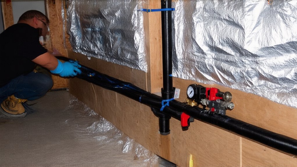
How to Install Water Underfloor Heating: A Practical Step‑by‑Step Guide
Start by measuring from the structural slab to thresholds so you can set the full build-up: DPM/vapour barrier, insulation, edging strip, pipe system, screed/panels, and floor finish, while maintaining required screed cover and insulation compressive strength. Choose a UFH system that suits screed, timber, or retrofit constraints. Design pipe spacing (100–200 mm), loop lengths, and zones from heat-loss calculations. Install insulation tight, fix pipes per drawings, then flush and pressure-test (typically 6 bar) before commissioning. Keep going to see detailed layouts, joint protection, and balancing tips.
Key Takeaways
- Measure slab-to-threshold height, then plan layers: DPM, insulation, edge strip, UFH pipe, screed/board, and final floor covering.
- Choose a UFH system suited to build-up and structure: screeded clip-rail/panels, timber diffuser plates, or thin overlays for retrofits.
- Design zones and pipe loops from heat-loss calculations; use 100–200 mm spacing and keep loop lengths within supplier limits for balancing.
- Install insulation tightly with taped joints, fit continuous perimeter edging, then fix and lay pipe without kinks, protecting crossings and marking circuit IDs.
- Connect circuits to the manifold, flush each loop, pressure-test to specified bar, record results, and keep pressure on during screeding if required.
Plan Your Water UFH Floor Build-Up and Height
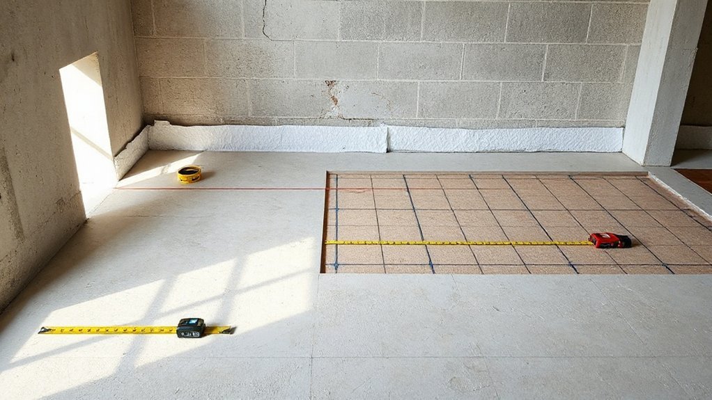
Before you fix pipe centres or choose a manifold location, you need to confirm the full UFH floor build-up and the finished floor level you must hit. Measure from structural slab to threshold, then allocate depth for insulation, vapour barrier/DPM continuity, edge strip, pipe, screed or low‑profile panel, and final covering.
Verify compressive strength of insulation and minimum screed cover to meet manufacturer instructions and relevant standards, and allow for movement joints.
Check door clearances, stair nosings, and appliance plinths so you don’t create trip hazards.
Lock in your Floor layout only after you’ve run Heating calculations for required output and surface temperature limits, then adjust build-up, not safety margins.
Record dimensions and tolerances for inspection and commissioning.
Choose a Water Underfloor Heating System for Your Floor
Once you’ve confirmed the available build-up and finished floor level, choose a hydronic UFH system that matches your floor construction, load limits, and heat output requirement without compromising compliance.
For screeded floors, use clip-rail or castellated panels with barrier pipe rated for temperature and pressure, and specify insulation meeting local energy regulations.
For timber or suspended floors, use low-profile diffuser plates or modular panels that protect joists and avoid exceeding allowable deflection.
In retrofits, consider thin overlay boards where door clearances are tight, but verify declared thermal resistance of coverings.
Select manifolds with flow isolation, air venting, pressure test points, and WRAS-approved components.
If you’re integrating Alternative energy sources, confirm compatible flow temperatures.
Pair thermostats with smart control systems and failsafe limits to prevent overheating.
Design Water UFH Pipe Spacing, Loops, and Zones
Because pipe layout controls both heat output and hydraulic balance, you should design your water UFH pipe spacing, loop lengths, and zones as a single, coordinated plan rather than as separate choices.
Start from your room-by-room heat loss and target floor surface temperature, then select spacing (typically 100–200 mm) to meet output without exceeding manufacturer limits.
Keep each loop length within the pipe supplier’s maximum and aim for similar lengths per manifold to simplify balancing and avoid excessive pump head.
Use a serpentine or spiral pattern consistently to manage temperature striping at edges.
Apply zoning strategies that match occupancy and glazing: separate high-load areas, bathrooms, and large spaces, and avoid mixing different floor coverings on one loop.
Document drawings, design flow rates, and control setpoints for commissioning and compliance.
Install Insulation, Edging Strip, and UFH Pipes
Although your pipe layout is already defined, you must install the insulation boards, perimeter edging strip, and UFH pipework to the manufacturer’s fixing method and the approved drawings so the system meets design output, stays hydraulically balanced, and complies with building and fire-safety requirements.
Prepare a clean, level sub-base and fit a DPM where specified. Lay thermal insulation tightly butt-jointed, staggered, and taped to prevent screed ingress and thermal bridging.
Install the edging strip continuously at all upstands, columns, and thresholds to allow expansion and reduce flanking losses.
Set clip-rail, staples, or fixing panels to the required centres, then uncoil pipe straight, avoiding kinks and minimum bend-radius breaches.
Fix at specified intervals, keep loop IDs readable, and protect pipe where it crosses movement joints or service penetrations.
Pressure-Test Water UFH and Connect the Manifold
With the insulation, edging strip, and pipe loops fixed to the drawings, you now need to prove the pipework is leak‑free and correctly identified before any screed or floor build‑up hides it.
Label each circuit, then connect flow/return tails to the manifold using the specified fittings and torque. Fit isolating valves, air vents, drain points, and fill/flush hoses.
Carry out Hydraulic testing with clean water, purging air circuit by circuit until clear flow returns. Pressurise to the design test pressure (typically 6 bar or 1.5× working pressure) using a calibrated gauge, then hold for the required period, checking every joint and pipe route for drops or weeps. Record results.
Keep the system under test pressure during screeding where specified. Complete System sealing, cap unused ports, and lock actuators closed until commissioning.
Conclusion
You’ve planned your build-up, chosen the right system, designed tight pipe spacing and sensible zones, and fixed insulation, edging, and pipes like a pro—now don’t get complacent. A sloppy manifold connection or skipped pressure test can turn a “simple” UFH job into a floor‑up, wallet‑emptying disaster. Pressure-test to spec, record results, and keep pipes pressurised during screeding. Purge air, balance circuits, and verify flow/return temperatures. Do it right, and your floor won’t just warm—it’ll perform flawlessly.…