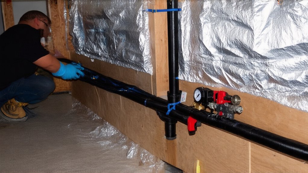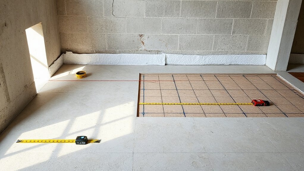
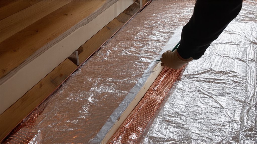
Retro‑Fitting Electric Underfloor Heating Without Lifting the Whole Floor
You can retrofit electric underfloor heating without lifting the whole floor by first confirming headroom, door clearances, subfloor dryness/flatness, and that you’ve got RCD protection and spare circuit capacity. Patch, prime, and self-level as needed, then dry-lay a low-profile mat/foil/loose cable, avoid overlaps, and log resistance tests. Route the floor sensor in its own conduit, encapsulate fully with approved leveller/adhesive, respect curing times, and commission by ramping temperatures—next you’ll see how system choice and floor finish change the method.
Key Takeaways
- Verify headroom, door clearances, subfloor flatness/dryness, and electrical capacity/RCD protection before committing to a retrofit system.
- Use low-profile heating mats, foil, or loose cable matched to your floor type to avoid full floor removal.
- Prep the existing subfloor: clean residues, repair cracks, prime, and apply self-levelling compound for a stable, flat bed.
- Plan cable routes and sensor conduit to avoid overlaps, fixtures, and kinks, and record layouts plus resistance readings.
- Encapsulate elements with approved adhesive/compound, respect minimum cover depths and curing times, then have an electrician complete final connections and commissioning.
Check If Your Room Suits Retrofit Electric Underfloor Heating

Before you buy a retrofit electric underfloor heating kit, confirm your room can handle the added height, power load, and moisture risk. Measure door clearances, skirting gaps, and threshold changes.
Then verify your subfloor is flat, rigid, and dry. Check existing floor build-ups for historical installation methods (e.g., bitumen residues, old screeds, or lath systems) that may need testing or remediation before bonding compounds are used.
Calculate the circuit load, confirm RCD protection, and verify the consumer unit has capacity for a dedicated fused spur and thermostat.
In wet zones, verify IP ratings, insulation resistance testing access, and compliant floor sensors.
If headroom or electrics fail checks, shortlist alternative heating solutions like upgraded radiators or infrared panels.
Choose a Low-Profile System: Mats vs Foil vs Loose Cable
Next, you’ll choose a low-profile electric UFH system by checking finished floor height limits, subfloor type, and the manufacturer’s minimum covering requirements.
Start by comparing low-profile mats for consistent watt density and faster layout on open areas. Then consider foil for floating laminate/engineered wood versus loose cable where you need tight turns, irregular zones, or spacing control.
Before you commit, you’ll verify RCD protection, thermostat sensor placement, and carry out insulation-resistance and continuity tests to keep the install safe.
Low-Profile Mats Comparison
How do you choose a low-profile electric underfloor heating system that delivers the output you need without forcing you to raise the floor? Start by comparing mat thickness (typically 3–5 mm) and watt density (usually 100–200 W/m²) against your room’s heat-loss.
Next, check the carrier type: mesh-backed mats suit tile adhesive and self-leveller; uncoupling-mat systems add crack isolation but can increase build-up.
Verify cable spacing is fixed and consistent for predictable output, and choose pre-sized mats to reduce on-site cutting (only cut mesh, never the cable).
Confirm IP rating, floor sensor compatibility, and RCD protection.
For Smart home integration, pick thermostats supporting scheduling.
Apply energy efficiency strategies by zoning rooms and using setback temperatures.
Foil Vs Loose Cable
Although low‑profile mats cover most tile and stone retrofits with minimal build‑up, you’ll choose between foil and loose cable when the floor type or layout demands a different approach.
Use Foil heating under floating laminate or engineered timber: first lay insulation underlay, then roll foil strips, tape joints, and keep them clear of fixings and thresholds. Next, route cold tails to a back box, and fit the floor sensor centrally between runs.
Choose Loose cable for awkward rooms, tight borders, or fixed fixtures: plan spacing to hit the watt density, then clip cable to a decoupling membrane or fixing strips without crossing or kinking.
Finally, test continuity and insulation resistance before, during, and after covering, and connect via RCD-protected circuit.
Add Retrofit Insulation Boards (Without Major Build-Up)
Before you lay heating mats or cables, fit thin retrofit insulation boards to cut downward heat loss without creating a big floor height build-up. Choose high‑compressive XPS or cement‑faced boards approved for floors and compatible with your levelling compound.
Vacuum and degrease the subfloor, then check it’s dry and sound; repair cracks so boards won’t rock. Dry‑lay to confirm coverage, then bond with a notched trowel using flexible tile adhesive or manufacturer‑specified primer/adhesive.
Stagger joints, keep edges tight, and tape seams with alkali‑resistant mesh. Add corrosion‑resistant fixings only where permitted and clear of future cable runs.
Skim‑coat for a flat surface. Pair with a smart thermostat to improve energy efficiency and limit overheating.
Calculate Floor Height, Door Clearance, and Trims
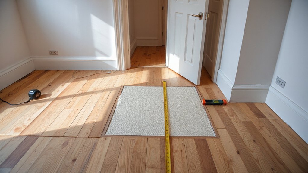
Once you’ve chosen your insulation boards and heating system, map the full floor build-up so you don’t trap doors, foul skirting, or create trip lips at thresholds. List each layer thickness: board, adhesive, mat/cable, primer, leveller, and your flooring materials. Add them, then compare to the existing finished floor line in every doorway and at stairs.
Next, measure door undercuts and swing clearance with a tape and feeler gauge; you’ll want at least 3–5 mm above the finished surface, more for rugs. Mark the required trim-off on the door, and plan for threshold strips where levels change.
Check skirting: either undercut it or remove and refit higher. Use installation tools like a straightedge, laser level, and calipers to verify totals.
Prep and Level the Subfloor for Electric UFH Longevity
Before you lay electric UFH, you’ve got to verify the subfloor is dry, dust-free, and free of oils or adhesives. You should wear a respirator and eye protection while vacuuming and abrading.
Patch cracks, fill voids, and replace any loose sections so you’re not trapping movement or moisture under the heating layer.
Then prime as specified and pour a self-leveling compound to a uniform thickness, keeping the area ventilated and off-limits until it fully cures.
Subfloor Moisture And Cleanliness
Because moisture and debris can trap heat and weaken adhesives, you’ll get a safer, longer‑lasting electric UFH retrofit by treating the subfloor like a controlled substrate, not “whatever’s under the covering.”
Start by removing all loose material (dust, paint flakes, old glue, oils) with a scraper and HEPA vacuum. Then check moisture with a meter and confirm it’s within the heating‑mat and levelling‑compound limits. Document readings across the room; don’t assume corners match the center.
Maintain subfloor moisture below the manufacturer maximum before you prime or bond anything. Verify cleanliness standards by wiping with a white cloth; if it picks up residue, vacuum again and degrease.
Keep the area dry, ventilated, and off‑limits until priming starts.
Spot Repairs And Patching
Where do retrofits fail fastest? At weak spots you didn’t repair—cracks, divots, loose boards, or hollow tiles—so your heater flexes, overheats, or delaminates.
Start by isolating power, then mark defects with chalk and measure depth with a straightedge. Vacuum dust, then abrade glossy areas for bond.
For timber, re-fix squeaky zones with screws into joists; don’t pierce existing services.
For concrete, chase cracks, remove friable edges, and fill with a compatible repair mortar or epoxy patch; feather edges flat. Verify flatness again and re-clean.
Keep cables away from patches until they cure. Log repairs for future maintenance tips and pair them with your Wireless control settings so heat ramps gently.
Self-Leveling Compound Application
Even if your subfloor looks “good enough,” a self-leveling compound (SLC) gives electric UFH the flat, fully supported bed it needs to avoid hot spots, cable lift, and premature delamination.
Vacuum dust, then prime per the SLC manufacturer—skip primer and you’ll trap bubbles or lose bond. Dam edges, seal gaps, and tape doorways so the pour can’t leak.
Set heating mats/cables per layout, protect the cold leads, and verify resistance before you bury anything. Mix with a paddle at the specified water ratio; overwater weakens the pour and hurts Energy efficiency.
Pour and gauge-rake to minimum cover, then spike-roll to release air. Keep traffic off until cured, then recheck resistance before hooking up your Smart thermostat.
Retrofit Electric Underfloor Heating Under Tile, Vinyl, and Laminate
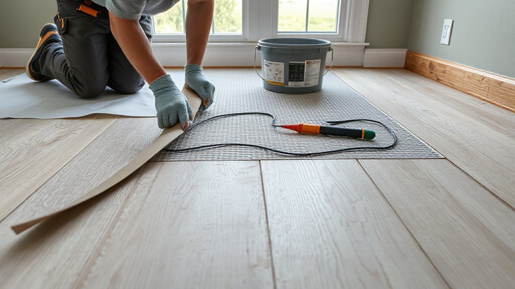
Although each floor finish has its own limits, you can usually retrofit electric underfloor heating under tile, vinyl, or laminate by adding a low‑profile heating mat or cable layer, embedding it in a thin levelling compound (or tile adhesive), and reconnecting it to a correctly rated thermostat on an RCD‑protected circuit.
First, confirm the substrate is sound, dry, and flat, then prime to suit the compound. For tile, trowel adhesive, bed the mat, and fully encapsulate to prevent voids and hot spots.
For vinyl, use a manufacturer‑approved smoothing compound to achieve a perfectly even surface and stay within maximum temperature limits.
For laminate, add an underlay rated for UFH and keep cable crossings impossible.
Plan routes around fixings, consider color options, and note maintenance requirements: record layouts and resistance readings.
Thermostat, Sensors, and Wiring (What to DIY vs Electrician)
Once you’ve encapsulated the mat or cable and recorded your resistance readings, focus on the control gear that makes the system safe and predictable: the thermostat, floor sensor, and fixed wiring.
Plan Thermostat placement first: mount it on an internal wall, away from sun, drafts, and heat sources, at a usable height.
Next, route the floor sensor in its own conduit from the thermostat box to the floor, ending centrally between two heating runs. Keep the sensor tip fully embedded and serviceable by leaving a gentle pull path.
DIY tasks: chase and fit back boxes, install conduit, label cold tails, and document routes.
Electrician-only: mains supply, RCD protection checks, fixed connections, and commissioning.
Prioritise Wiring safety: isolate circuits, use correct cable sizes, and verify continuity and insulation resistance.
Common Retrofit UFH Mistakes: Hotspots, Cracked Tiles, Failed Adhesive
Before you switch the system on, work through the retrofit failure points that cause hotspots, cracked tiles, and adhesive breakdown: uneven mat coverage, poor heat transfer through the levelling layer, and using the wrong adhesive/grout for thermal cycling.
First, dry-lay and measure spacing; don’t overlap cables, kink them, or bridge expansion joints. Keep consistent coverage around fixtures to avoid cold rings and local overheating.
Next, prime properly and pour a manufacturer-approved, fully encapsulating leveller; trapped air insulates and concentrates heat. Maintain minimum cover depth and cure time before tiling.
Then, select flexible S1/S2 adhesive and grout rated for UFH; rigid products shear as the floor expands.
Finally, commission gradually: ramp temperature daily, log resistance readings, and verify sensor placement for energy efficiency, especially in historic design retrofits.
Conclusion
You’ve checked suitability, picked a low‑profile mat/foil/cable, added slim insulation, and confirmed height, doors, and trims. Now prep: clean, prime, and level the subfloor so the heater sits flat and lasts. Install the correct build‑up for tile, vinyl, or laminate, then test resistance and insulation before and after covering—write readings down like it’s a telegraph log. Fit the floor sensor correctly, and leave final connections and RCD protection to a qualified electrician.…